zynq xc7z030 board – FII-PE7030 Experiment 6 – Use of Multipliers and ISIM
Experiment 6 Use of Multipliers and ISIM
6.1 Experiment Objective
- Learn to use multiplier
- Use ISIM to simulate design output
6.2 Experiment Implement
- 8×8 multiplier, the first input value is an 8-bit switch, and the second input value is the output of an 8-bit counter.
- Observe the output in ISIM
6.3 Experiment
6.3.1 Program Design
The first step: the establishment of the main program framework
| module mult_sim(
input inclk_p, input inclk_n, input [7:0] sw, output [15:0] mult_res, output reg [7:0] count ); endmodule |
The second step: call multiplier IP core
Refer to experiment 1. Call the multiplier IP core in the IP core directory, as shown in Figure 6.1. Enter mult in the search field to find Multiplier.
Double-click to select the multiplier configuration interface shown in Figure 6.2. Configure the multiplier IP core according to the parameters in the figure.
In the Basic window:
- Component Name: mult_8x8
- Data Type: Signed
- Width: 8
Under the Output and Control window, as shown in Figure 6.3:
Pipeline:1
Others are set by default.
Click OK and follow the steps to generate the multiplier IP core.
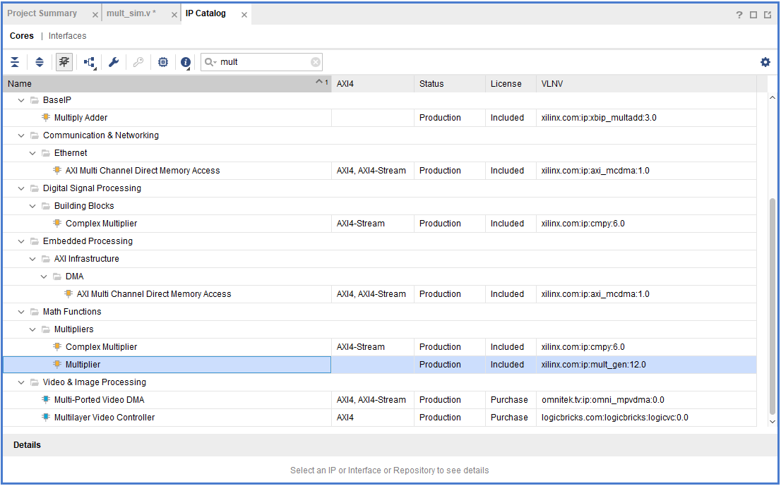
Figure 6.1 Search multiplier IP core
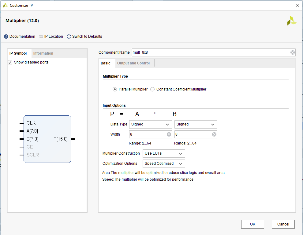
Figure 6.2 Multiplier input parameter settings
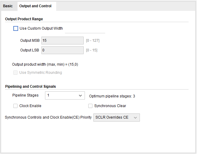
Figure 6.3 Multiplier output settings
The third step: instantiate the multiplier into the design file
| wire pll_locked;
wire sys_clk; reg sys_rst; mult_8x8 mult_8x8_inst( .CLK (sys_clk), .A (sw), .B (count), .P (mult_res) ) always @ (posedge sys_clk) sys_rst <= !pll_locked; always @ (posedge sys_clk) begin if (sys_rst) count <= 8’d0; else count <= count +1’b1; end |
6.4 Compile and Call of ISIM Simulation and Modelsim Simulation Library
Under the Vivado platform, you can choose to use built-in simulation tool ISIM or third-party simulation tools for functional simulation of the project. Simulating with the Modelsim simulation tool requires a separate compilation of the simulation library. This experimentd uses the built-in ISIM tool emulation and briefly introduce Modelsim’s Xilinx simulation library file compilation for simulation using Modelsim.
The first step: build simulation project files
Add simulation source files in the Sources window of the main interface of Vivado, click Desgin Sources, select the Add Sources command in the pop-up floating window, select the Add or create simulation sources check box in the pop-up dialog box, create a new source file, refer to experiment 1, the file is named mult_sim_tb, as shown in Figure 6.4.
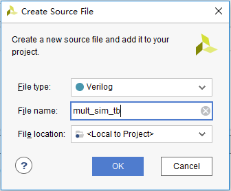
Figure 6.4 New simulation testbench file
After the creation is successful, the created testbench file will be automatically added in the sim_1 folder under the Sources window, as shown in Figure 6.5. Double-click to enter the design interface for design.

Figure 6.5 Create a simulation file.
The simulation file is as follows:
| module mult_sim_tb;
// Define the simulation signals reg inclk_p; reg inclk_n; reg rst; reg [7:0] sw; wire [15:0] mult_res; wire [7: 0] count; // Instantiate the simulation module mult_sim mult_sim_inst( .inclk_p (inclk_p), .inclk_n (inclk_n), .rst (rst), .sw (sw), .mult_res (mult_res), .count (count) ); // Initialize the simulation signals initial begin rst = 0; inclk_p = 1; sw = 0; #5 rst = 1; #15 sw = 20; #20 sw = 50;+ #20 sw = 100; #20 sw = 101; #20 sw = 102; #20 sw = 103; #20 sw = 104; #50 sw = 105; $monitor(“%d * %d=%d”, count, sw, mult_res); #1000000 $stop; end always begin #5 inclk_p=~inclk_p; inclk_n = !inclk_p; end endmodule |
The second step: run simulation
After saving the source file, find and expand the SIMULATION option under the Flow Navigator window on the main interface of Vivado, click Run Simulation, and click the Run Behavioral Simulation command in the pop-up floating window to start the ISIM simulation. The simulation interface is shown in Figure 6.6, the operation result mult_res appears one clock cycle later than the counter count.
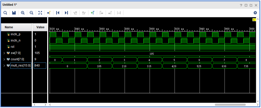
Figure 6.6 Simulation interface
Modelsim simulation library compilation:
When using Modelsim simulation, after installing Modelsim, the Xilinx simulation library file needs to be compiled first. The specific procedure is as follows
- Select compile simulation libraries under Tools in the menu bar, the following interface pops up shown in Figure 6.7.
- Set a full English path in the blue square in Figure 6.7. This path is to store the Modelsim and vivado joint simulation library files to be compiled and generated.
- Set as shown in the red sqaure in Figure 6.7, and select Modelsie (modelsim refers to the modelsim_se version. This version is a non-OEM version of the simulation tool launched by Mentor. Compared with the OEM version, it has a faster simulation speed and the number of simulation code lines are unlimited.) win64 under the installation path (select the win32 folder to install the x86 format Modelsie software). The joint simulation library of modelsim and vivado can be built. Click compile to start compiling the simulation library. The compiled library file is stored in the path set by the blue square in Figure 6.7.
- As shown in Figure 6. 8, the compilation is completed. Note that the process is very time consuming.
- More to practice
- Design an 8-bit trigger, simulate with ISIM
- Learn to write testbenches for simulation
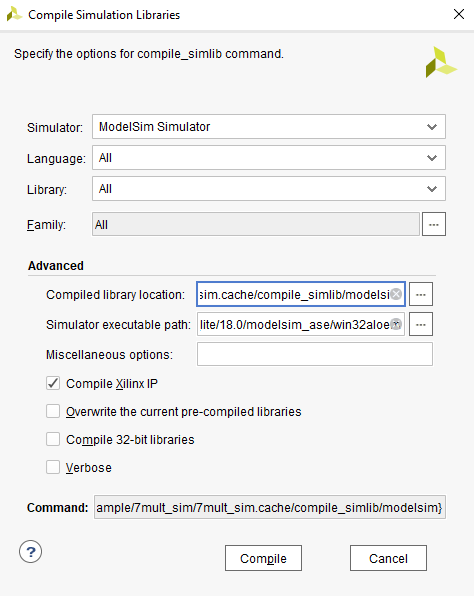
Figure 6.7 Compile library address settings
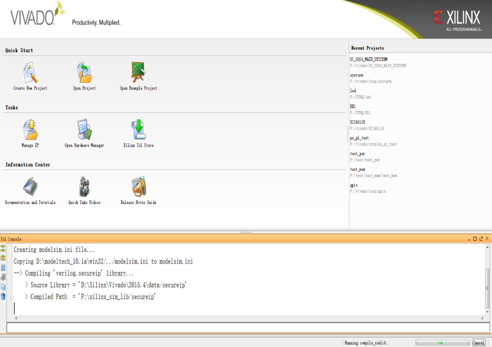
Figure 6.8 Successfully compiled the simulation library