Using PetaLinux to Transfer a Linux System
Table of Contents
Section 2: Formatting the SD Card 6
Section 3: Connecting to the Board and Booting Up 12
Section 1: Getting Set Up
*In order to follow along to this tutorial, you will be required to have Ubuntu 16.04.01 already installed on your Virtual Machine using Oracle’s VirtualBox. Because this tutorial is geared towards Ubuntu 16.04.01, using other versions may have differences between the execution of commands.
You will also need to have PetaLinux as well as TFTP already installed. In this tutorial, PetaLinux is installed in /home/ubuntu/PetaLinux. Make sure you change your path and directory in the commands accordingly.
First, we will need to configure the .bashrc file for PetaLinux. We can do this by executing the following command to append a pathway shortcut.
echo “alias sptl=‘source /home/ubuntu/PetaLinux/settings.sh’”
We can then verify that this is the case by executing the following command:
gedit .bashrc
You should see the following at the end of the file that shows up. If it isn’t there, please write it in.
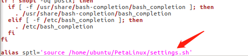
After confirming that it is there, we can go ahead and close the file. Restart the system for the changes to be applied.
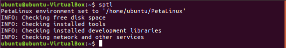
We will now execute the sptl command from the Terminal, like so:
Next, we will proceed to create a new workspace for the project. We can do this by using the following command. We will call our project testproject.
petalinux-create -t project –template zynq -n testproject
![]()
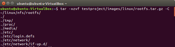
We will copy the existing FPGA project file to a folder called work in our home directory and delete the compressed file after extraction. We can verify that the file is there by executing the following command:
ls work
![]()
Next, we will navigate to the project directory by using the cd command on the project directory we just specified.
cd testproject
We will then open the FPGA file by using the following command, you may need to change the name of you FPGA file, as mine is FII_7030.sdk.
petalinux-config –get-hw-description ~/work/FII_7030.sdk/
The system configuration page would then be displayed after loading.
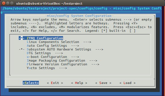
Because we will be booting from an SD card, please go to Image Packaging Configuration and Root filesystem type, and change it to SD Card. Exit by pressing [esc] twice or selecting the on-screen <Exit> prompt. When asked if you wish to save changes, please select Yes. You will be returned to the Terminal, where the project will be setup. This will take time.
Next, we will go on to configure the kernel. We will execute the following commands:
petalinux-config -c kernel
When the ARM configuration page comes up, you may choose to make corresponding changes. We will select <Exit>.
Next, we will execute the following command for Rootfs configuration:
petalinux-config -c rootfs
We will select <Exit>.
We will execute the following command to build the system:
petalinux-build
Note that this may take a while.
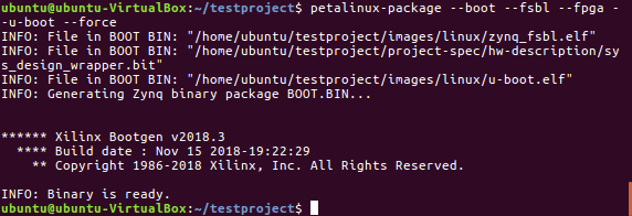
Finally, we will use the following command to create the boot file.
petalinux-package –boot –fsbl –fpga –u-boot –force
Section 2: Setting up the SD Card
We will need to format the SD card so the system will properly boot from it.
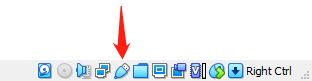
Plug in the SD card to your computer. If the SD card doesn’t show up in VirtualBox Ubuntu, simply navigate to the bottom right of the running virtual machine, and right-click on the USB. You can then choose your SD card.
We will be using the Ubuntu disks application to help us format the disk.
In order to allow Linux to be able to boot from the SD card, we will need to have two partitions on the SD card. One partition using the FAT32 format to hold the boot files, while the other uses the EXT4 format to store the root file system. The FAT32 partition needs to have the name of BOOT, while the EXT4 partition needs to have the name of rootfs.
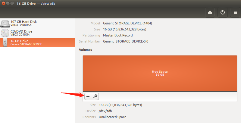
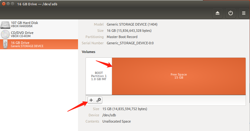
First, we will open disks. Next, we will select the SD card, and click on the add partition button.
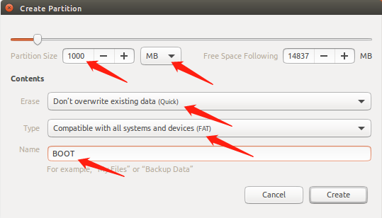
Next, we will change the Partition Size to 1000 MB,
change Erase to Don’t overwrite (you may also choose the other option, but it will take longer),
change Type to FAT,
and change the Name to BOOT.
We will now proceed to format the rootfs partition.
First, we will click on the free space, and click on the add partition button.
Next, we will change Erase to Don’t overwrite (you may also choose the other option, but it will take longer),
change Type to Ext4,
and change the Name to rootfs.
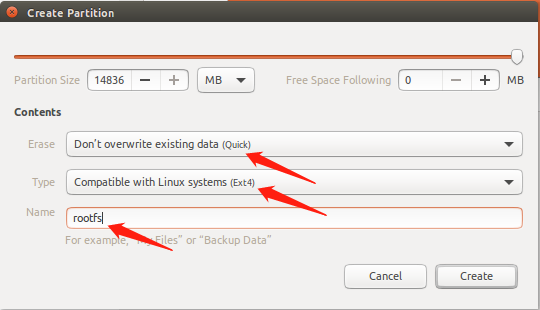
When you are all done, it should look something like this:
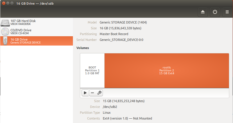
You may notice the two USB icons in the taskbar. Click on them to mount the two partitions to the Ubuntu system.
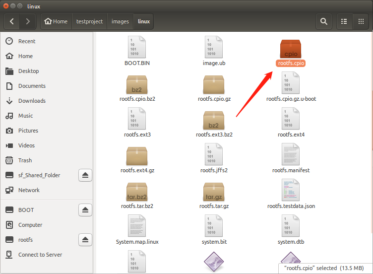
Next, we will go into the following directory: Home / testproject / images / linux
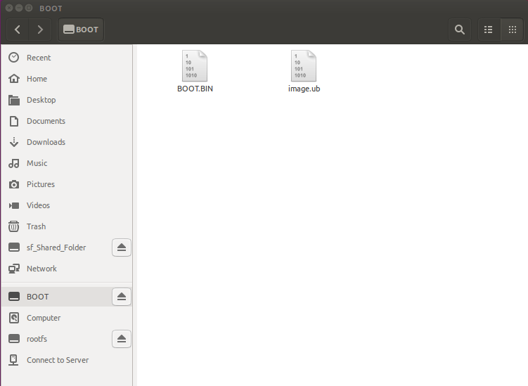
First, we will copy BOOT.BIN and image.ub to the BOOT partition.
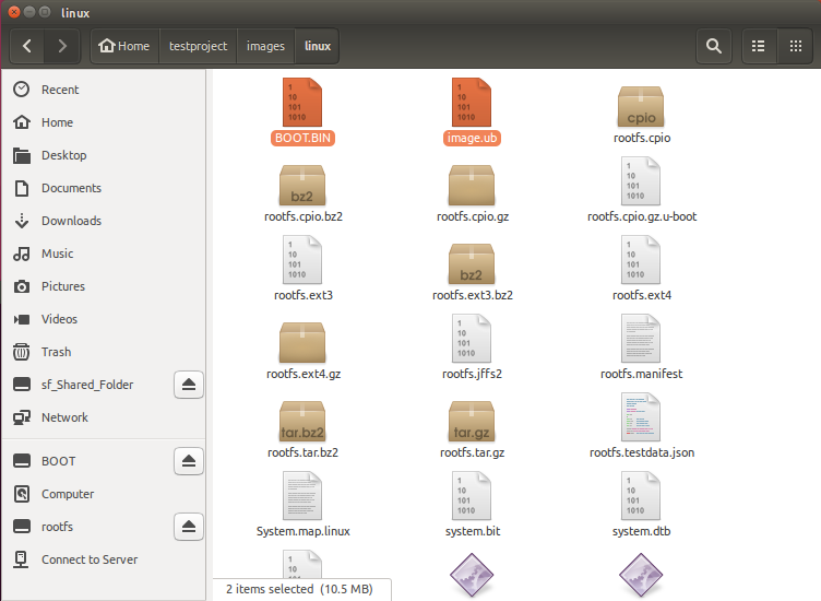
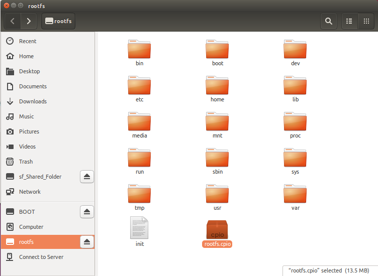
Next, we will copy the rootfs.cpio file to the rootfs partition.
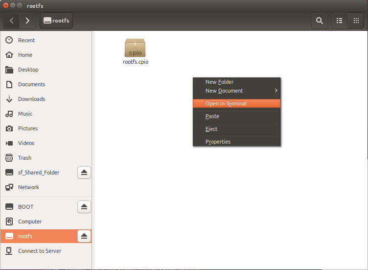
Next, we will right click the rootfs folder page, and select Open in Terminal.
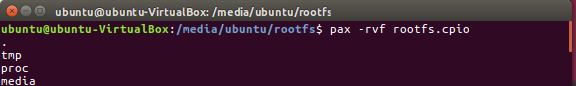
Once in the Terminal, we will execute the following command to extract the files:
pax -rvf rootfs.cpio
We can go ahead and delete the package when the extraction is complete.
You may eject the SD card when you are done and insert it into the development board.
Section 3: Connecting to the Board and Booting Up
You can now open up PuTTY and connect to the board.
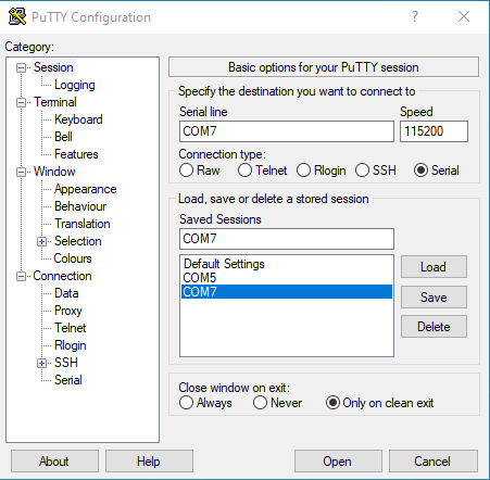
Notice that you may have a different port than here. You may also need to press the reset button on your development board for the system to boot from the SD card.
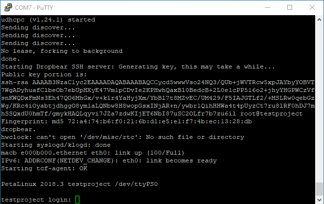
When prompted to log in, first enter your username, followed by your password. In my case, both username and password are “root”.
You can now use the ifconfig command to see the IP address of the system.
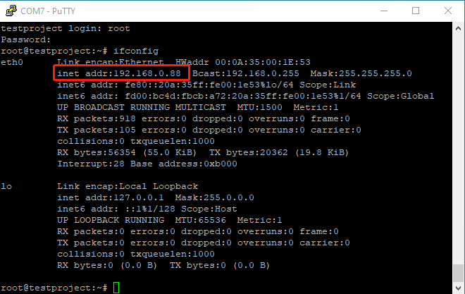
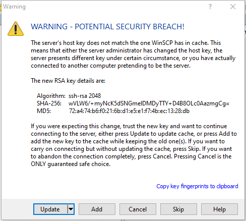
Now, we are able to use WinSCP to connect to the system and transfer as well as modify files.
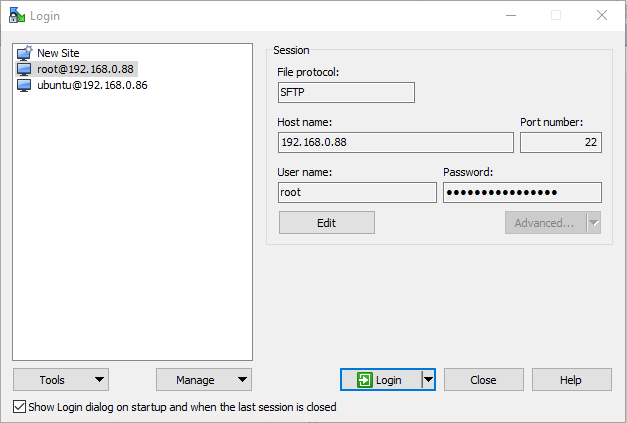
Make sure the IP address matches up, and you may simply select “update” if you get an error message.
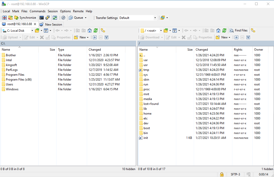
You can now work with the system files.
© 2020 Fraser Innovation Inc ALL RIGHTS RESERVED
Without written permission of Fraser Innovation Inc, no unit or individual may extract or modify part of or all the contents of this manual. Offenders will be held liable for their legal responsibility.
Thank you for purchasing the FPGA development board. Please read the manual carefully before using the product and make sure that you know how to use the product correctly. Improper operation may damage the development board. This manual is constantly updated, and it is recommended that you download the latest version when using.
Official Shopping Website: