


Description
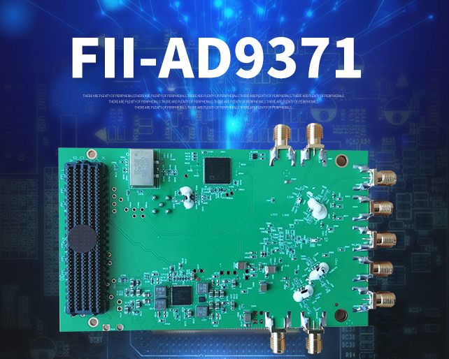
FII-AD9371 (completely compatible with ADRV9371-W/PCBZ ) are radio cards designed to showcase the AD9371, a high performance wideband integrated RF transceiver intended for use in RF applications such as 4G basestation, test and measurement applications and software defined radios.
FII-BD9371 (completely compatible with ADRV9371-W/PCBZ board ) is a single board with integrated transceiver AD9371 and its supporting power supply, radio frequency and digital interface, which is a high-performance, highly integrated RF transceiver board, suitable for 3G to 5G base station and test equipment, software-defined radio SDR and other RF application fields, the programmability and broadband capabilities of the module make it an ideal choice for a variety of transceiver applications. Transceiver For Use With AD9371, AD9528, ADP5054.
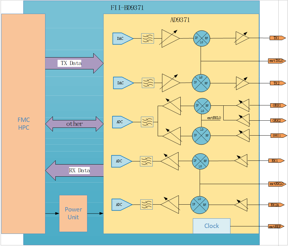
2. The module sets the RF front end, mixer, frequency synthesizer and high-speed analog-to-digital conversion device to provide a configurable FMC-HPC digital interface for the processor or FPGA, thereby simplifying the design. The operating frequency range of the RF chip is 300 MHz to 6 GHz, and the single channel bandwidth range is up to 100 MHz.
The radio cards provide hardware engineers, software engineers and system architects with a single 2×2 transceiver platform for device evaluation and rapid prototyping of radio solutions. All peripherals necessary for the radio card to operate including a high efficiency switcher only power supply solution, and a high performance clocking solution are populated on the board.
- Complete Radio Card platform containing AD9371 with:
- 2 x Transmit outputs
- 2 x Receive inputs
- 2 x Observation inputs
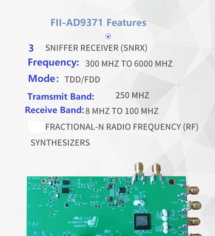
- 1x Sniffer path
- Narrow tuning range and Wide tuning range options
- ADRV9371-W/PCBZ matched for 300MHz – 6GHz
- Complete with high efficiency power supply solution and clocking solution for AD9371
- FMC connector to Xilinx ZC706 motherboard (EK-Z7-ZC706-G).
- Powered from single FMC connector
- Includes schematics, layout, BOM, HDL, drivers and application software
| Frequency | 300MHz ~ 6GHz |
|---|
| Type | Transceiver |
|---|
| Base Part Number | ADRV9371 |
|---|
| For Use With/Related Products | AD9371, AD9528, ADP5054 |
|---|

Hardware specifications and indicators
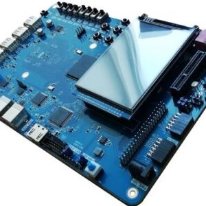
1. Appearance and physical size
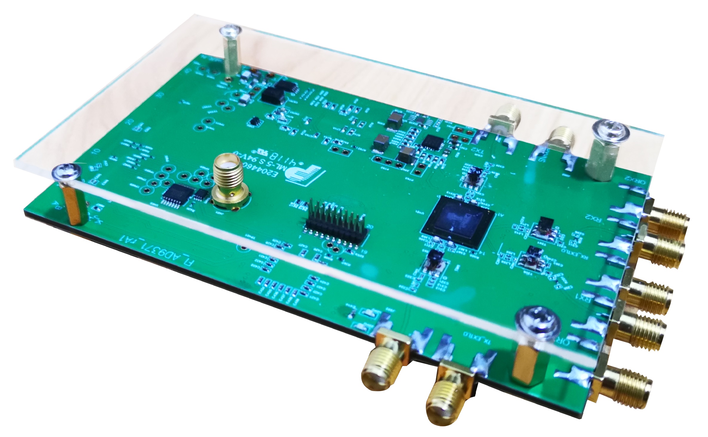
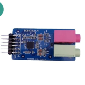
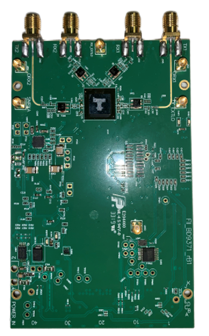 BD9371 physical picture (without protective cover)
110CM X 70CM
2.Board hardware RF parameter index
| Hardware RF parameter specifications | Hardware index |
| Transmission frequency range | 300 MHz to 6 GHz |
| Receive frequency range | 300 MHz to 6 GHz |
| RF bandwidth | 200 kHz to 100 MHz |
| Adjustable range of transmission gain | 40dB |
| Tunable receive gain | 30dB |
| Maximum transmit power | 0-5dBm |
| Number of transmitting channels | 2 |
| Number of receiving channels | 2 |
3. Working environment parameter index
| Work environment project specifications | Hardware index |
| Power supply | 12V |
| Operating temperature | -20℃ to 45℃ |
| humidity | 2%~98%(Normal temperature) |
| Power consumption | Typical value 9.0W |
Advantages and Features:
1. Tunable transmit and receive frequencies: transmit: 300 MHz to 6 GHz, receive: 300 MHz to 6 GHz
2. Tunable transmit and receive bandwidth: 200 kHz to 100 MHz
3. The transmit power and receive gain can be tuned: transmit: >40dB receive: >30dB
4. High transmit power and good broadband flatness, better than similar products on the market.
5. Power supply and data transmission through standard FMC-HPC connector
6. Support MIMO function, 2 channels transmit and 2 channels receive
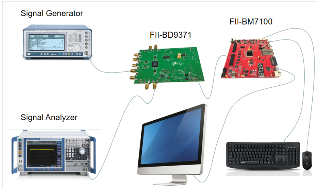
7. Can be combined with FII-BM7100 or other platforms that support FMC interface for software radio applications
| Datasheets |
|---|
Video FileGNU Radio Conference 2016 – Radio Architecture Design Challenges
Peripheral Interface
| Interface Type | description | Definition |
| SMA-F | TX1A,TX2A | 2 x RF transmission channel (same frequency) |
| SMA-F | RX1A,RX2A | 2 x RF receiving channel (same frequency) |
| SMA-F | ORX1,ORX2 | 2 x RF receiving observation channel |
| SMA-F | SNRXA | RF receiving detection channel |
| SMA-F | TX_EXTLO | Externally transmitted local oscillator |
| SMA-F | RX_EXTLO | External receive LO |
| SMA-F | EXTREF | External reference clock |
| HPC FMC | FMC | Please refer to the schematic diagram, universal RF data transmission interface, compatible with most similar products in the market |
Test scenario
Test data reference (some items)
1. Output Power And Flatness Test
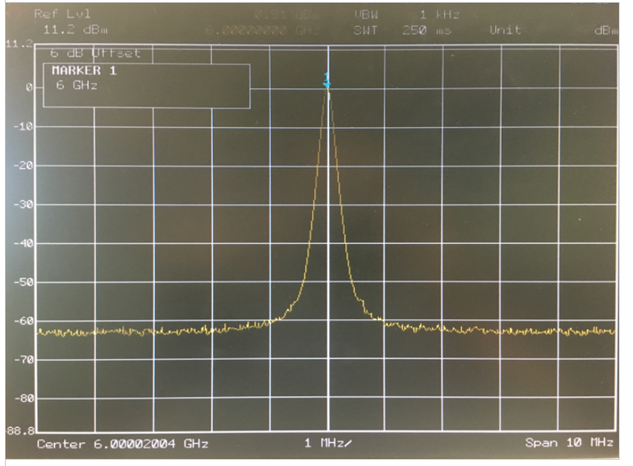 Test summary: The above picture is a screenshot of some tests. The frequency range covers from 300MHz to 6GHz, the output power is 0-6dBm, and the high-performance RF balun design ensures high bandwidth and high flatness.
2. Phase noise test
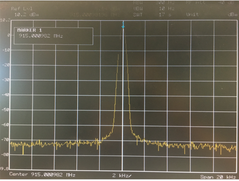
 Test summary: The above picture is part of the test screenshots. The frequency range covers from 300MHz to 6GHz. The typical values of phase noise are 90dBc/1KHz, 100dBc/10KHz. The perfect phase noise ensures high-quality communication test requirements. (The actual measurement is slightly lower, and the loop bandwidth 300KHz needs to be set to achieve the best performance.)
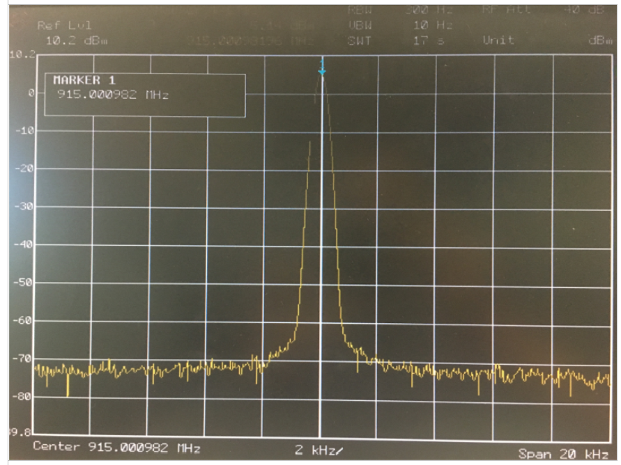
3. IQ modulation function test
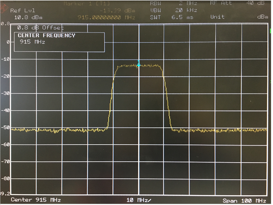 Test summary: The picture above shows the spectrum output of the IQ signal QPSK modulation signal at the frequency of 915M and 20M, and the IQ modulation function is normal
If you have any questions, you can contact us or post in the FII-AD9361 product forums. If you can not register to post, please let us know and I will create a forum username for you.
Reviews
There are no reviews yet.