RISC-V Instruction Set Explanation
V1.0
Fraser Innovation inc
RISCV instruction set explanation
Version Control
| Version | Date | Description |
| V1.0 | 2020/11/27 | Initial Release |
Copyright Notice:
© 2020 Fraser Innovation Inc ALL RIGHTS RESERVED
Without written permission of Fraser Innovation Inc, no unit or individual may extract or modify part of or all the contents of this manual. Offenders will be held liable for their legal responsibility.
Thank you for purchasing the FPGA development board. Please read the manual carefully before using the product and make sure that you know how to use the product correctly. Improper operation may damage the development board. This manual is constantly updated, and it is recommended that you download the latest version when using.
Official Shopping Website:
https://fpgamarketing.com/FII-PRX100-D-ARTIX-100T-XC7A100T-RISC-V-FPGA-Board-PRX100-D-1.htm
Content
1. General-Purpose Register and PC
2. RISC-V base instruction formats
3. I-type
4. U-type
5. R-type
6. J-type
7. B-type
8. Load & Store
9. Address alignment
10. Handle overflow situations
1. General-Purpose Register and PC
The CPU contains 32 general-purpose registers, sometimes they are called general-purpose register files. As shown in Figure 1-1, the general-purpose registers are named X0-X31, the value of the first register X0 is always 0, and the registers X1-X31 are readable and writable. There are 32 General-Purpose registers in total. The number 0-31 behind X0-X31 is called the index. The index can also be understood as the address of the register. When an instruction needs to use the General-Purpose Registers, The registers can be found by the index. The following chapters will have a dedicated FPGA program to organize the reading and writing of register files. For a 32-bit system, the width of all general-purpose registers is 32bit.
PC (program counter) is the program counter and also a register. Inside CPU, the PC register is not put together with the above 32 general-purpose registers, and the PC is not included in the register file. The value of XLEN is generally related to the CPU architecture. If it is a 32-bit architecture CPU, then the value of XLEN is 32. In Figure 1-1, XLEN-1 = 32-1 = 31, which means that the highest bit in a general-purpose register is 31. In a 64-bit CPU, the width of the general-purpose register is 64, and the width of the PC is also 64 bits, the highest bit is 63.
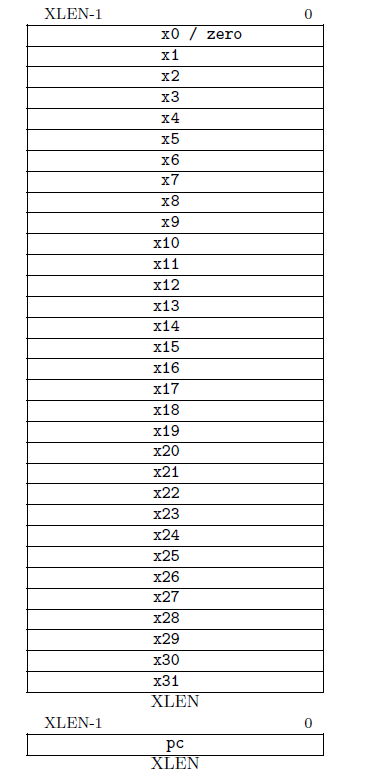
Figure1-1 General-Purpose Register and pc structure diagram
2. RISC-V base instruction formats
RV32I can be divided into six basic instruction formats. R-type instructions for register-register operations, an I-type instructions for immediate and load operations, and S-type instructions for store operations. B-type instructions for conditional branch operations. U-type instructions for long immediate and J-type instructions for unconditional jumps.
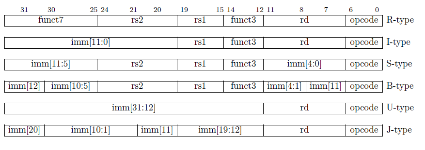
Figure 2-1 Assembly instruction machine code format
R-type:
R-type is an operation without immediate. The immediate is the number that exists as an integer in the instructions. The binary format of the R-type assembly instruction machine code is shown in Figure 2-1. The length of a binary instruction is 32bit. The 7 bits from 0 to 6 are opcode (operation code), used to identify the type of instruction. Bits 7 to 11 are the index of the rd register. The Rd register is also called the destination register, and the destination register is the register used to store the result. rs1 and rs2 are called source registers. In most cases, instructions need to read the values of the two source registers for operations. The index of rs1 is in bits 15-19, and the index of rs2 is in bits 20-24. The following is an example of how to use the register index.
Example: When the value of the position index of rd in the instruction is 5’b00011, which is 3 in decimal notation. After the CPU receives this instruction, it will detect that the value of the 7-11bit position is 3, and it will find the X3 register as the rd register in the 32 general-purpose registers, and finally write the result to the x3 register. If the index of rs1 and rs2 is 2 and 4 at the position of bit 15-19 and bit 20-24 in the binary assembly instruction at this time, the CPU will detect that the value of the corresponding position of rs1 and rs2 in the instruction is 2 and 4, then x2 and x4 are found in 32 General-Purpose Registers. Read values from registers x2 and x4 and perform operations.
This instruction requires opcode plus funct3, and sometimes funct7 together to determine the type of operation that this instruction allows the CPU to perform.
R-type:
The R-type command format is very clear. In the actual encoding process, the arrangement of encoding positions is meaningful. For example, the encoding position of the three register indexes in different instruction formats are always the same. Index of Rd is at 11-7, Index of rs1 is at 19-15, and Index of rs2 is at 24-20. This is their fixed position. Some instructions may not be useful. The index to the partial register. For example, there is no rs2 in the second instruction type I-type, but there are rs1 and rd and their indexes are in the corresponding positions. For another example, in s-type funct3 is at bits 14-12. The opcode is available in all instruction formats, and the position remains unchanged, always bit 0-6.
I-type:
The upper 12 bits of I-type is an immediate number. The opcode is different from other instruction formats because the corresponding specific operations are different, and other parts are very similar to R-type.
S-type:
The characteristic of S-type instruction is that there is no rd register. In this type of instruction, the immediate is divided into two parts, the first part is in bit11-5, and the second part is in bit4-0. The 5 bits of the immediate 4-0 occupy the position of rd in other instruction formats, and 5-11 occupy the position of funct7. Explain that the command format does not need to write back. That is, read the two values from the two registers and perform the operation together with the immediate, and write the result to the register after the operation is over.
U-Type
A 20-bit immediate is provided in the U-type instruction. The final operation result is related to the 20-bit immediate, and the result is written back to the rd register. The opcode determines the type of operation. There are no funct3, rs1, rs2, and funct7 in U-type. This type of instruction structure is very simple.
B-Type
B-type instructions are mainly used as branch instructions, but they are conditional Branch. It means to decide whether to jump or not need to depend on whether the condition is valid. The B-type machine code structure is shown in Figure 2-1. The instruction does not include rd register and funct7, but contains rs1, rs2, funct3 and immediate. The immediate is divided into two areas. The encoding of B-type instruction immediate is out of order. The reason is not described in detail here. There is a specific article on the official site explaining why it is out of order. In short, it has been verified that the effect on CPU operation function when the immediate number sequence is in this order is very well. But the immediate is disrupted, so it will be decoded when the CPU executes in the future. After decoding, the CPU needs to restore the disrupted immediate in order. For example, when the CPU gets a B-type instruction, the immediate in it is scrambled, and the CPU needs to arrange the immediate in the order of 12-1 to restore the immediate.
J-Type
The format of this instruction is very similar to U-type, it only have Rd register and immediate and opcode. At the same time, the immediate of J-type is also disrupted. That means that the CPU must first put the immediate numbers together to restore the original immediate numbers when decoding.
3.I-type
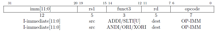
Figure3-1 I-type format
There are 15 instructions in total for I-type. Now introduce the first 6 instructions. Please refer to Figure 3-1 for I-type command format. The opcode corresponding to the I-type instruction is named OP-IMM. It means immediate operation code (IMM: immediate).
The immediate opcode OP-IMM==7’b001_0011. When opcode==OP-IMM==7’b001_0011, it proves that the instruction is an I-type instruction, and the specific behavior of this instruction is determined by the value of funct3.
The following part describes the instructions in I-type one by one.
ADDI:ADDI rd,rs1,imm[11:0]
ADD stands for addition, I stands for immediate, and the ADDI instruction means addition with immediate. This instruction adds the value in the rs1 register to the immediate, and then stores the result of the addition in rd. ADDI corresponds to funct3 == 3’b000, which means that funct3==3’b0000 in the I-type instruction means that the instruction is an ADDI instruction.
A new concept pseudo-instruction is introduced here, taking the MV instruction as an example.
MV:MV rd,rs1
MV (move) instruction. This instruction is to move the value in rs1 to rd. There is a move instruction in x86 and also in mcs51. What are pseudo instructions? Pseudo instructions are instructions that do not exist in the assembly instruction set. These instructions are convenient for assembly programmers and are often used. For example, in the assembly program, there are often shifts between registers. So the MV instruction is often used. Take the MV instruction as an example, its actual meaning is ADDI rd, rs1,0. That is to say, the value in the rs1 register is added up with the immediate 0 , and finally stored in the rd register. Because the value of rs1 does not change after rs1 is added to zero, the MV instruction moves the value of rs1 to rd. The programmer can write such a pseudo-instruction MV when writing the assembler. The compiler software will translate this instruction into ADDI rd, rs1, 0 when the program is compiled, and then send the ADDI instruction to the CPU to run.
SLTI:SLTI rd,rs1,imm[11:0]
In the second instruction SLTI, S stands for Set, and its role is to set rd. Set the value in the rd register to 0 or 1. It should be noted that in the instruction, if the condition is satisfied, the bit is set to 1, and if the condition is not satisfied, the bit is set to 0. The setting condition of this instruction is LT: less than. I stands for immediate. So the judgment condition is whether the value of rs1 is less than the immediate. Because the rs1 register is 32-bit in all operations, and the immediate in this instruction is 12-bit, the immediate must be expanded first, and then the operation will be performed after the expansion. Note that the extensions here are all signed extensions.
Here is an example to explain the signed extension. For example, there is a 12-bit immediate. If the highest bit is 0, it means that the immediate is positive. If the highest bit is 1, it means that the immediate is negative. When the positive number is sign-extended, the upper 20 bits are all filled with 0, and when the negative number is sign-extended, the upper 20 bits are all filled with 1.
SLTIU:SLTIU rd,rs1,imm[11:0]
In the instruction SLTIU, U represents an unsigned number. It means to set after comparing unsigned numbers.
Example: Compare 8-bit binary numbers. -1: 8’b1111_1111, -2:8’b1111_1110. When compared as a signed number, -2<-1, if it is used as an unsigned number, the comparison is still valid, but if you use -2 and +1 8’b0000_0001 to compare an unsigned number. At this time, 1111_1110>0000_0001. (254>1)
Pseudo-instruction SEQZ:SEQZ rd,rs1 (SLTIU rd,rs1,1)
If rs1==0, then rd is set to 1.
This pseudo-instruction is a special case of SLTIU and will be used frequently.
ANDI: ANDI rd,rs1,imm[11:0]
The immediate is expanded to 32 bits as a signed number, then perform AND with rs1 after the extension, and store the result in rd.
ORI: ORI rd,rs1,imm[11:0]
The immediate is expanded to 32 bits as a signed number and do OR with rs1. The result is written into rd.
XORI: XORI rd,rs1,imm[11:0]
The immediate is expanded to 32 bits as a signed number and do XOR with rs1. The result is written to rd.
The format reflects the flexibility of instructions. The format does not mandate which register rs1 and rd are, and programmers need to select registers from 32 general-purpose registers when writing assembly programs.
Pseudo-instruction NOT:NOT rd,rs1 (XORI rd,rs1,12’hfff)
NOT is a negation instruction. The function is to reverse the value in rs1 and store it in rd. It will be translated into (XORI rd,rs1,12’hffff)
The assembly instruction format and corresponding funct3 are shown in Figure 3-2 below

Figure3-2 some I-type assembly instructions and funct3 machine code
Shift instruction
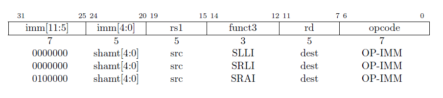
Figure3-3 Shift instruction
- SLLI rd,rs1,shamt[4:0]
SLLI :shift left logical by shamt(shift amount) ,The number of shifts is determined by imm “4:0”. This instruction means to shift the value of rs1 to the left in shamt[4:0], use 0 to fill the low bits of rs1, and write the result to Rd.
2. SRLI rd,rs1,shamt[4:0]
SRLI:shift right logical .Shift the value in rs1 to the right by shamt[4:0] bits, add zero to the high bits of rs1, and write the result to rd.
3. SRAI rd,rs1,shamt[4:0]
SRAI:Arithmetic shift right, shift the value in rs1 to right by shamt[4:0] bits, the high bits of rs1 are filled with the original rs1[31], and the result is written into rd.
Note that the OP-IMM and funct3 codes of SRLI and SRAI are the same. The difference is the instruction by the value of imm[11:5], as shown in Figure 3-3
4. U-type
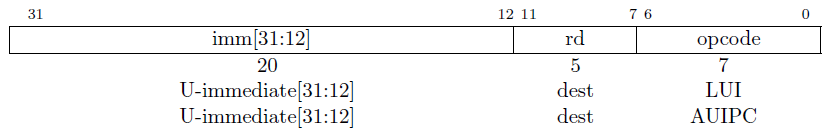
Figure4-1 U-type instruction machine code format
- type instructions include opcode, rd, 20-bit immediate. As shown in Figure 4-1.
- LUI rd,U_imm
LUI is identified by opcode. The opcode name is LUI and the value is 7’b011_0111. This instruction writes U_imm into the high 20 bits of rd, and the low 12 bits of rd will be filled with 0.
- AUIPC rd,U_imm
AUIPC is identified by opcode, the opcode name is AUIPC, and the value is 7’b001_0111. The instruction is to place the 20-bit immediate in the high 20 bits of the 32-bit, and add the low 12 to the current PC and write it into the rd register. PC is the program counter.
The above two instructions can form a high 20-bit offset. With JAL, JALR, and conditional jumps, any jump in the 32-bit space can be achieved.
We will introduce JAL, JALR, and conditional jumps in subsequent chapters.
5. R-type
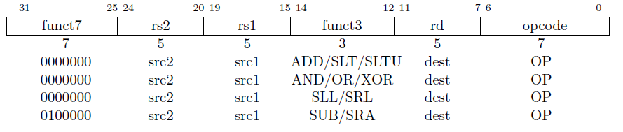
Figure5-1 R-type instruction machine code format
There are 10 R-type instructions in total. The opcode name is OP and the value is 7’b011_0011. Small instructions are determined according to funct3, and if it is not enough, funct7 is used to determine. As shown in Figure 5-1, it can be found that it is similar to the immediate instruction.
1.ADD rd,rs1,rs2
addition
funct7==7’b0000000;
funct3==3’b000;
This instruction writes the result of rs1+rs2 into rd, ignoring overflow (overflow can be handled by software).
2.SLT rd, rs1,rs2
Funct7==7’b0000000;
funct3==3’b010 ;
rs1 and rs2 are compared with signed numbers, if rs1<rs2, rd is set to 1, otherwise it is set to 0
3.SLTU rd,rs1,rs2
Funct7==7’b0000000;
funct3==3’b011 ;
Use the unsigned number to compare rs1 and rs2, if rs1<rs2, rd is set to 1, otherwise it is set to 0
4.AND rd,rs1,rs2
funct7==7’b0000000;
funct3==3’b111;
Write the result of rs1&rs2 into rd, where & means that rs1 and rs2 are AND together bit by bit
5. OR rd, rs1,rs2
funct7==7’b0000000,
funct3==3’b110
Write the result of rs1|rs2 into rd, where | means or
6. XOR rd,rs1,rs2
funct7==7’b0000000,
funct3==3’b100 ;
Write the result of rs1^rs2 to rd, where ^ means rs1 XOR rs2 bit by bit
7. SLL rd,rs1,rs2
Logical shift left
Funct7==7’b0000000,
Funct3==3’b001;
Shift rs1 logically to the left according to the number specified in the lower 5 bits of rs2, fill in the lower bits with zeros, and write the result to rd
8. SRL rd, rs1,rs2
Logical shift right
Funct7==7’b0000000,
funct3==3’b101 ;
rs1 is logically shifted to the right according to the specified number of low 5 bits in rs2, and the high bits of rs1 are filled with zeros, and the result is written into rd
9. SRA rd,rs1,rs2
Arithmetic shift right
Funct7==7’b010_0000,
funct3==3’b101 ;
Arithmetic shift rs1 to the right according to the specified number of low 5 bits in rs2, the high bit is determined by the original rs1[31], and the result is written into rd. Note: When shifting, only the value of RS1 is copied to the temporary variable for shifting, and the original value remains constant.
10. SUB rd,rs1,rs2
Subtraction
funct7==7’b010_0000,
funct3==3’b000;
Write the result of rs1-rs2 to rd, ignore overflow (overflow can be handled by software)
The only difference between addition and subtraction instructions is funct7
Addition funct7==7’b000_0000
Subtraction funct7==7’b010_0000
6. J-type
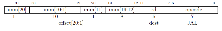
Figure6-1 J-type instruction machine code format

Figure 6-2 J-type diagram of immediate recovery
JAL jump and link
JAL rd, label
opcode==7’b110_1111
Unconditional jump and link instructions
Use J-type format
Save the address of the next instruction (PC+4) to the rd register, and then set the PC to the current value plus the sign bit extension offset. The default Rd register is x1. The label is an address label, programmer can name the label. It is essentially an address. Label is the address where JAL instruction jumps to.
The arrangement of immediate seems a bit messy, this is because the main purpose is to keep the position of opcode, rd , some immediate same as other instruction formats.
Immediate recovery: inst[31], as shown in Figure 6-2, inst[19:12] in the figure represents the position of the immediate in the instruction, so the encoding and decoding are strictly consistent. The encoding is done by the instruction compiler, and the decoding is done by the hardware circuit of the CPU. The following chapters will introduce the RTL implementation of RISC-V. Note that the low bit is filled with 0 when restoring immediate.
The 20-bit immediate is an integer multiple of 2, which is added to the PC after sign extension, imm[31:0]+PC forms an offset, and the addressing range is ±1M
Rd=PC+4 rd is the link register
Examples and explanations of the compilation process:
Example: There is currently an assembly instruction SUB x8, x3, x5, which should be converted into the binary format of the assembly instruction. sub determines that the opcode is 011_0011. If rd is x8, the position of rd in the binary code is 01000. The value of sub at the funct3 position is 3’b000. rs1 is x3, the value of the corresponding position is 00011, rs2 is x5, then 24:20 is 00101. Finally, SUB instruction fills 010_0000 in the funct7 position.
Note that the underscore in the number itself has no meaning, just for the convenience of users to read, for example, 0000_0001 is equal to 00000001.
Before jumping in the Jal instruction, the PC value needs to be compared with the address marked by the label, and the difference is stored in imm. When jumping, imm+PC forms an offset, and the range is +-1M (20 bits). At the same time, save the current PC value +4 to rd.
Question: Why does the PC add 4?
Answer: There is a difference of 4 between the addresses of the storage units in the instruction storage space (corresponding to 32 bits and 4 bytes). Adding 4 means that the address of the next instruction is stored in the rd register.
JALR
Jump and Link register
Note that JALR use I-type format
opcode==7’b110_0111
funct3==3’b000
JALR rd,rs1,imm[11:0]
rd=PC+4 rd
As a link register, generally use register x1 or register x5.
The 12-bit immediate is extended by the sign bit and added to the value of rs1, and the lowest bit of the result is set to zero to form a jump offset.
JAL and JALR can form a pair of instructions to complete the function call and return.
For example, there exist a command jal x1, 80000040, when running this command, rd is x1. Store pc+4 in x1. The program jumps to the address 0x80000040 and runs. When this part of program is over, you need to use the command jalr x2, x1, 0x0; jump back, then choose x1 as rs1 in the jalr command. Now the immediate is 0, if the immediate is not zero, you need to change After immediate is expanded, it is added to x1 to get a value as an address, and the program jumps to this address. In general, jal and jalr form a pair of instructions to complete the function call and return.
7. B-type
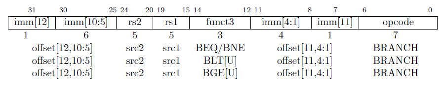
Figure7-1 B-type Instruction machine code format
B type instruction, B: branch instruction. These jump instructions are conditional.
There are 6 conditional jump instructions, as shown in Figure 7-1
Opcode==7’b110_0011
BEQ rs1,rs2,label //(imm)
funct3==3’b000
Imm is a 12-bit immediate, which is an integer multiple of 2, sign extended to 32bit
Instruction function: If rs1==rs2, the jump offset is PC+imm, and the jump range is ±4K
Note that the feature of this instruction is that there is no rd, so the instruction does not record the current PC value before jumping.
As shown in Figure 7-1, it can be found that the immediate in the instruction does not have the 0th bit. Therefore, if the instruction jumps, it will jump at least 2 steps, for example, it can jump to 0x80000002 or 0x80000004, but not to 0x80000001 or 0x80000003. 1 address corresponds to 1 byte == 8bit space, because the shortest instruction of RISC-V is a 16-bit compressed instruction set, the default jump is 16bit==2byte , and the lowest bit is 0 by default.
Also note that the actual size of immediate after adding 0 is 13 bits, and the highest bit imm [12] is the sign bit. If the highest bit is 0 then jump backward, if the highest bit is 1 then jump forward. Jump range is 4K.
BNE rs1,rs2, label
label==PC+imm[12:1]
funct3==3’b001
If rs1!=rs2, the jump offset is PC+imm, and the jump range is ±4K
BLT rs1,rs2, label
Funct3=3’b100
First do signed comparison If rs1<rs2, the jump offset is PC+imm, and the jump range is ±4K
BLTU rs1,rs2, label ;
—label==imm[12:1]
funct3=3’b110
First do unsigned comparison, if rs1<rs2, the jump offset is PC+imm, and the jump range is ±4K
BGE rs1,rs2, label ;
—label==imm[12:1]
funct3=3’b101 //GE — great or equal
First do Signed comparison, if rs1≥rs2, the jump offset is PC+imm, and the jump range is ±4K
BGEU rs1,rs2, label;
—label==imm[12:1]
funct3=3’b101
First do unsigned comparison, if rs1≥rs2, the jump offset is PC+imm, and the jump range is ±4K
8. Load & Store
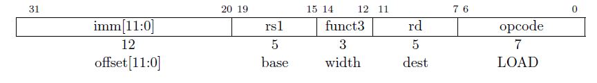
Figure8-1 LOAD instruction machine code format (I-type)
The instructions that mentioned before are all register instructions, and LOAD & STORE are instructions of the memory. In the load part, the value must be obtained from the memory, such as ROM, EPROM, EEROM, FLASH, DDR, SRAM, and other memory.
There are 15 instructions for I-type, 5 instructions for LOAD
LW rd, offset(rs1) ;
L:load, w:word。Word 4byte or 32bit。
—offset==imm[11:0]
opcode==7’b000_0011
funct3=3’b010
Read a copy of 32bit data from the memory and store it in the rd register //LW —load word (32 bit)
The memory address is expanded by 12-bit immediate and added to rs1
LH rd,
LH H: half-word corresponds to 16bit
offset(rs1);
—offset==imm[11:0]
opcode==7’b000_0011
funct3=3’b001
Read the copy of 16bit data from the memory and store it in the rd register after sign bit extension //LH load half word
LHU rd, offset(rs1);
—offset==imm[11:0]
opcode==7’b000_0011
funct3=3’b101
Read the copy of 16bit data from the memory, expand by high bit 0, and store it in the rd register
LB rd, offset(rs1)
opcode==7’b000_0011
funct3=3’b000
Read a copy of 8bit data from the memory, after sign bit extension, store it in the rd register
LBU rd, offset(rs1);
—offset==imm[11:0]
opcode==7’b000_0011
funct3=3’b100
Read the copy of 8bit data from the memory, expand by high bit 0, and store it in the rd register
STORE 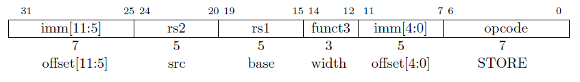
Figure8-2 S-type command format
The store instructions use S-type format. The store instruction writes the value to the memory, s-type does not have rd.
STORE type include 3 instructions
opcode==7’b010_0011
SW rs2, offset(rs1);
—offset==imm[11:0]
funct3=3’b010
Copy the value of rs2 to the memory, the address calculation is the same as the LOAD instruction
SH rs2, offset(rs1)
—offset==imm[11:0]
funct3=3’b001
Copy the value of the lower 16 bits of rs2 to the memory. The address calculation is the same as the LOAD instruction. The upper 16 bits are not needed and can be ignored.
SB rs2, offset(rs1)
—offset==imm[11:0]
funct3=3’b000
Copy the value of the lower 8 bits of rs2 to the memory, the address calculation is the same as the LOAD instruction.
9.Address alignment
As mentioned earlier, the lowest bit of the jump instruction is automatically filled with 0 by default. This also represents data alignment. If it is 32bit data, the lower 2 bits of the address alignment are zero. This corresponds to the automatic increase of 4 to the PC value. Adding 4 in binary means adding 100, you can see that the lower 2 bits are 00.
Question: Why does the lowest digit of the jump instruction default to 0 instead of the lowest digit of zero?
Answer: The current system is a 32-bit system. But the RISC-V instruction set supports compressed instructions, that is, it supports a 16-bit instruction set, and the data is 16 bits, so only the lowest bit defaults to 0. RISC-V has no 8-bit instruction set.
For example, to read data from the memory, the first storage unit address is 0x80000000, the second address is 0x80000004
10. Handling of overflow situations
In the above chapter, it is mentioned that the ADD, ADDI, SUB and other three instructions may overflow in the calculation. The following examples show how to deal with them.
RISC-V user manual does not explain how to deal with the overflow situation, but it is recommended to deal with it at the software level.
1. Unsigned number addition overflow
ADD X5, X6, X7: x5=x6+x7 The addition of two unsigned numbers (actually positive numbers) cannot be smaller than the original value. If this happens, overflow has occurred, and the program needs to jump to the overflow handling function Partial operation, BLTU x5, x6, overflow.
2. Add signed numbers, but one of the operands is known to be a positive number,
The same judgment jump. Because a number plus a positive number cannot be smaller than the original valuer.
ADDI x5,x6,+imm BLT x5,x6, overflow
3. Under normal circumstances, whether the number is positive or negative is not known at all. After adding, you need to judge whether x7 is less than zero and record it. slti x28,x7,0; When x7 is less than 0, the value of x28 is set to 1, which proves that x7 is a positive number. If x7 is negative, the value of x28 will be set to 0. Instructions slt x29, x5, x6. Compare the values of x5 and x6 and store the result in x29. If x5 is less than x6. Then x29 is set to 1. Finally, if x28 and x29 are not equal, the overflow will overflow. Discuss in several situations.
A. Both x28 and x29 are 1. Prove that x7 is negative and x29 is 1. Prove that x5 is less than x6. It is true because adding a negative number must increase and decrease
B. Both x28 and x29 are 0. X7 is a positive number, x5>=x6, plus the positive number gets bigger and bigger.
C. X28 is 1, and x29 is 0. It is impossible to increase by adding a negative number, so overflow occurs.
D. X28 is 0, x29 is 1, and it is impossible to decrease by adding a positive number, so overflow occurs.
As for the processing method, it is processed in the software according to the specific situation.