
Xilinx Risc-V Board Tutorial : Multiplier Use and ISIM Simulation- FII-PRX100 FPGA Board Experiment 7
Experiment 7 Multiplier Use and ISIM Simulation
1.Experiment Objective
-
- Learn to use multiplier
- Use ISIM to simulate design output
2.Experiment Design
-
- Build new project mult_sim
-
-
- Select device XC7A100TFGG676-2
-
-
- Design requirement
- 8×8 multiplier, the first input value is an 8-bit switch, and the second input value is the output of an 8-bit counter.
- Observe the result on Modelsim
- Observe the result on 6 segment decoders
- Design procedure
- Create new file mult_sim.v
- Add PLL,set the input clock to be 50 MHz, and the output clock to be 100 MHz
- Add LPM_MULT IP
- Build new project mult_sim
IP Catalog -> input Mult in the search box. Invoke the multipliers. See Fig 7. 1.
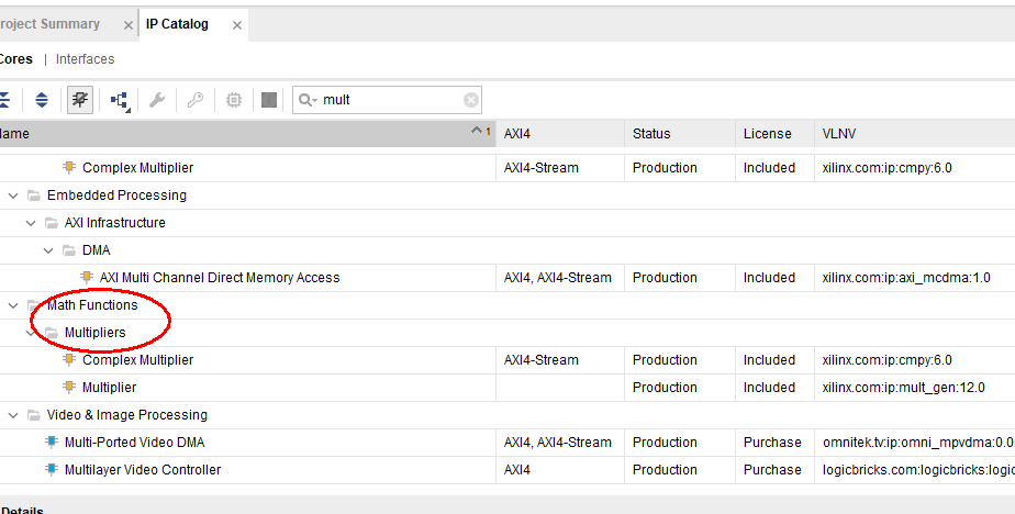
Fig 7. 1 Build IP core for multiplier
-
-
- Choose input data type to be unsigned. See Fig 7. 2.
-
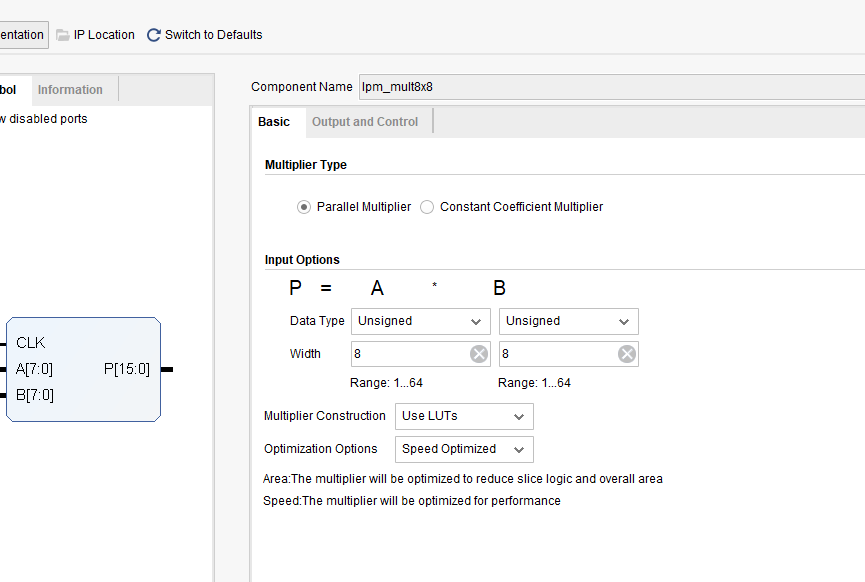
Fig 7. 2 Set the input data type and data width
-
-
- Choose Pipelining and Control Signals. See Fig 7. 3. Add a delay of 1 stage. The default optimum stage is 3 stages.
-
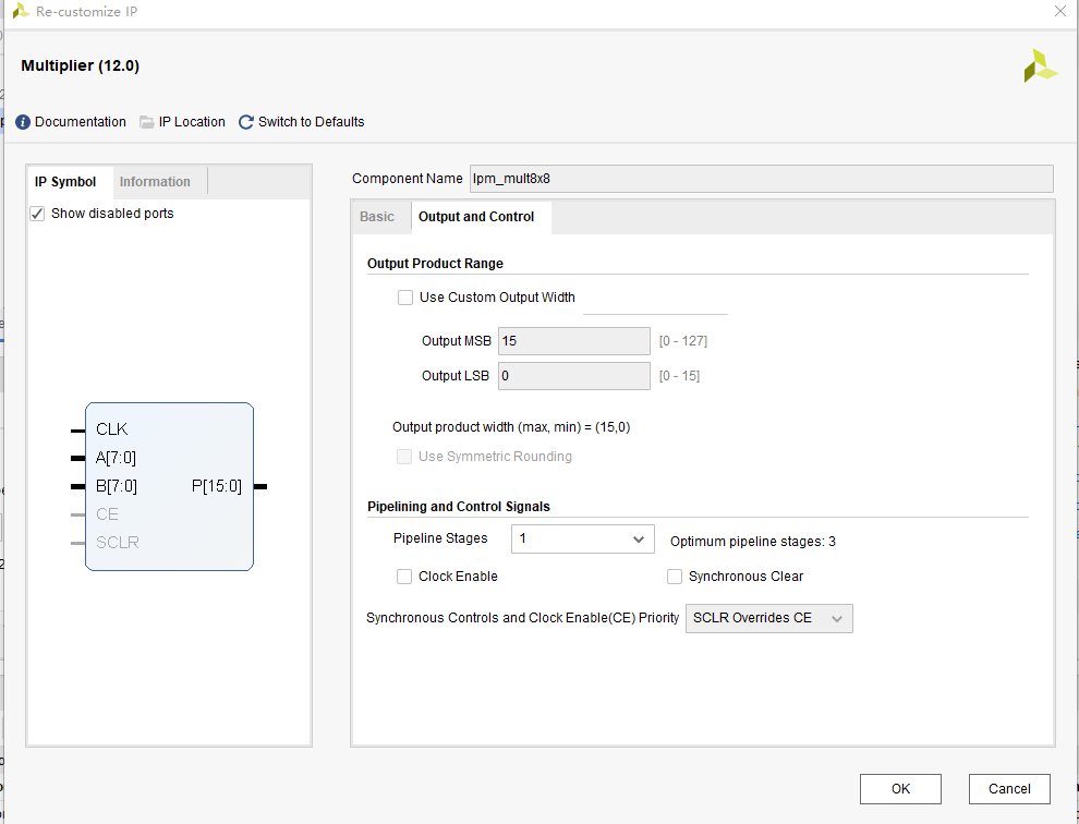
Fig 7. 3 Pipelining setting
-
- Choose default for other settings
- Instantiate in the top-level entity
3.The Top-level Entity Is as Follows:
| module mult_sim
( input rst, input inclk, input [7:0] sw, output [6:0] seven_seg, output [3:0] scan ); wire [15:0] mult_res; wire sys_clk; wire sys_rst; reg [7:0] count; always@(posedge sys_clk) if(sys_rst) count<=0; else count<=count+1; lpm_mult8x8 ( .clock (sys_clk), .dataa (sw), .datab (count), .result (mult_res) ); pll_sys_rst pll_sys_rst_inst ( .inclk (inclk), .sys_clk (sys_clk), .sys_rst (sys_rst) ); endmodule |
4.ISIM Simulation Library Compilation and Call
Under the Vivado platform, you can choose to use built-in simulation tool ISIM or third-party simulation tools for functional simulation of the project. Simulating with the Modelsim simulation tool requires a separate compilation of the simulation library. This routine uses the built-in ISIM tool emulation and briefly introduce Modelsim’s Xilinx simulation library file compilation for simulation using Modelsim.
- Build simulation project. Tools -> Compile Simulation Libraries. See Fig 7. 4 for the popup window.
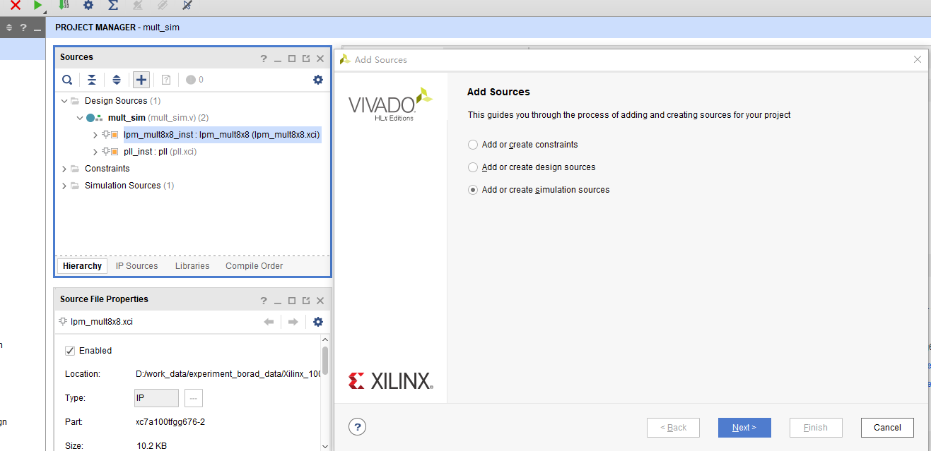
Fig 7. 4 Compilation library address setting
Simulation testbench code is as follows:
| module mult_sim_tb;
//Define simulation signals reg rst_n; reg [7:0] sw; reg clk; wire [7:0] seven_seg; wire [3:0] scan; wire [15:0] mult_res; wire [7: 0] count ; mult_sim mult_sim_inst ( .rst_n(rst_n), .inclk(clk), .sw(sw), .count(count), .mult_res(mult_res), .seven_seg(seven_seg), .scan(scan) ); initial begin rst_n=0; clk = 1; sw = 0; #5 rst_n=1; #15 sw = 20; #20 sw = 50; #20 sw = 100; #20 sw = 101; #20 sw = 102; #20 sw = 103; #20 sw = 104; #50 sw = 105; $monitor(“%d * %d=%d”, count, sw, mult_res); #1000000 $stop; end always #10 clk=~clk; endmodule |
- As shown in Fig 7. 5, after the simulation stimulus file is added, ISIM can be started in Simulation->Run Simulation –> Run Behavioral Simulation on the left side of the project management.
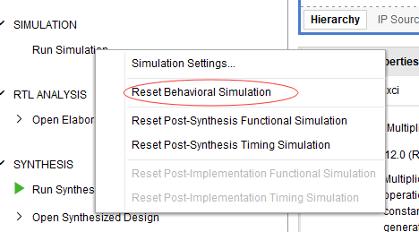
Fig 7. 5 Simulation library compiled
- Simulation result is shown in Fig 7. 6.
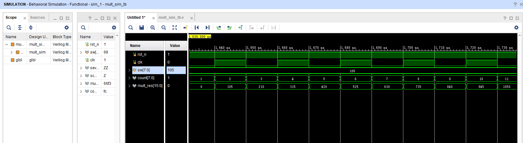
Fig 7. 6 Simulation result
- Compile ModelSim library
After installing ModelSim, compile the Xilinx simulation library file first. The specific process is as follows:
-
-
- Tools -> Compile Simulation Libraries. See Fig 7. 7 for the popup window.
-
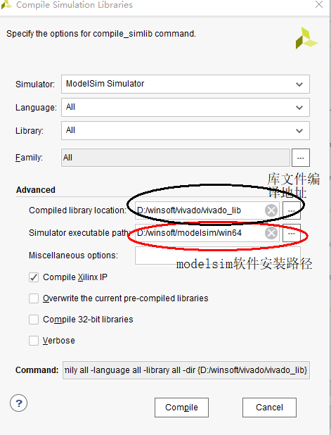
Fig 7. 7 Compilation library address setting
-
-
- As shown in Fig 7. 8, the compilation is completed. Note that the process is very time consuming.
-
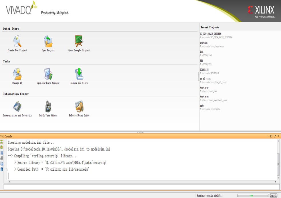
Fig 7. 8 Simulation library compiled
Approachable advanced information for ModelSim can be referred online. Here would not go into more details.
- More to practice
- Design an 8-bit trigger, simulate with Modelsim
- Learn to write testbenchs for simulation

