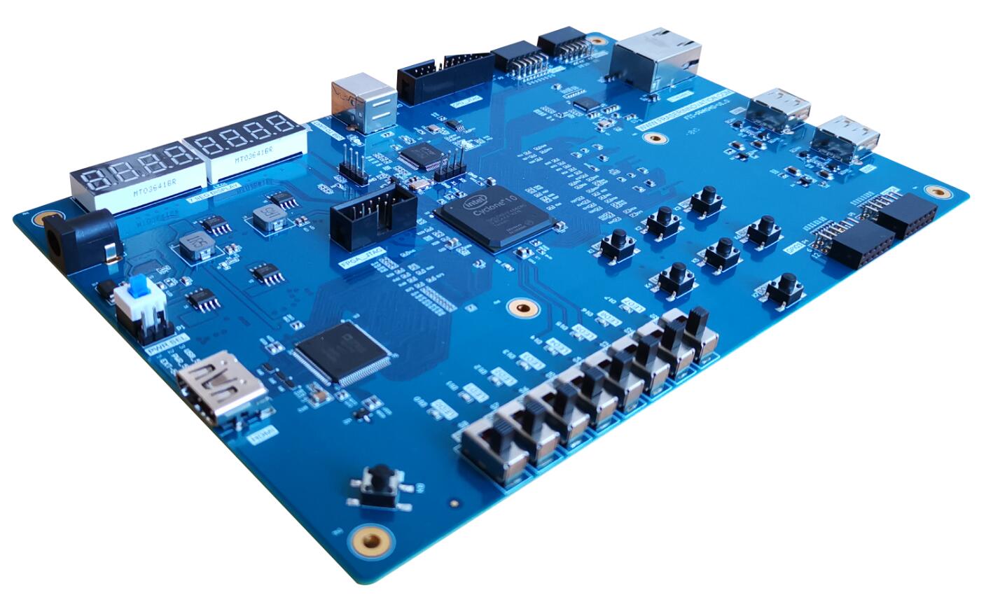
FII RISC-V3.01 CPU FII-PRA040 FII-PRX100-S FII-PRX100D Risc-V Risc-V Core Risc-V Tutorial

RISC-V Instruction Set Explanation

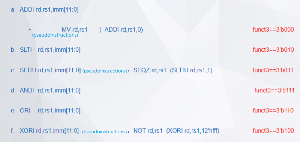
V1.0 Fraser Innovation inc RISCV instruction set explanation Version Control Version Date Description V1.0 2020/11/27 Initial Release Copyright Notice: © 2020 Fraser Innovation Inc ALL RIGHTS RESERVED Without written permission of Fraser Innovation Inc, no unit or individual may extract or modify part of or all the contents of this manual. Offenders will be held liable for their legal responsibility. Thank you for purchasing the FPGA development board. Please read the manual carefully before using the product and make sure that you know how to use the product correctly. Improper…

Read More
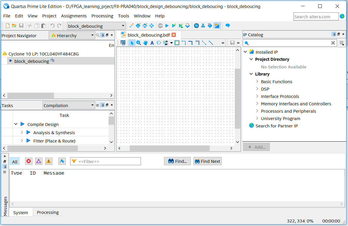
Graphic Design Interface
Experimental Manuals FII-PRA040 FPGA Board Based FPGA Tutor Risc-V

Combined With the BCD_Counter Project to Achieve the Display of the Digital Clock, Master the Design Method of Graphics From Top to Bottom – Block/SCH – Altera Risc-V Board PRA040 Experimental 4

Experiment 4 Block/SCH 4.1 Experiment Objective Review building new FPGA projects in Quartus, device selection, PLL creation, PLL frequency setting, Verilog’s tree hierarchy design, and the use of SignalTap II Master the design method of graphics from top to bottom Combined with the BCD_counter project to achieve the display of the digital clock Observe the experimental results 4.2 Experiment Implement Use schematics design to build the project. 4.3 Experiment This experiment is mainly to master another design method. The other design contents are basically the same as the experiment 3…

Read More
Experimental Manuals FII-PRA040 FPGA Board Based FPGA Tutor Risc-V Risc-V Core

Frequency Division Design, Learn the BCD Code Counter, Digital Display Decoding Design, Segment Display – Altera Risc-V Board PRA040 Experimental 3

Experiment 3 Segment Display 3.1 Experiment Objective Review experiment 1, proficient in PLL configuration, frequency division design, and project verification; Learn the BCD code counter; Digital display decoding design; Learn to program the project into the serial FLASH of the development board; 3.2 Experiment Implement The segment display has two lower digits to display seconds, the middle two digits to display minutes, and the highest two digits to display hours. The decimal point remains off and will not be considered for the time being. 3.3 Experiment 3.3.1 Introduction to the…

Read More
FII RISC-V3.01 CPU FII-PRA040 Risc-V Risc-V Core

Learn to Analyze the Captured Signals, Practice the Use of SignalTap Logic Analyzer in Quartus – SignalTap – Altera Risc-V Board PRA040 Experimental 2

Experiment 2 SignalTap 2.1 Experiment Objective Continue to practice the use of the development board hardware; Practice the use of SignalTap Logic Analyzer in Quartus; Learn to analyze the captured signals. 2.2 Experiment Implement Use switches to control the LED light on and off Capture and analyze the switching signals on the development board through the use of SignalTap. 2.3 Experiment 2.3.1 Introduction of DIP Switches and SignalTap Introduction of switches The on-board switch is 8 DIP switches, as shown in Figure 2.1. The switch is used to switch the…

Read More
Experimental Manuals FII RISC-V3.01 CPU FII-PRA040 FPGA Tutor Risc-V Risc-V Core

Master the Design of the Frequency Divider to Implement the Shifting – LED LED Shifting – Altera Risc-V Board PRA040 Experimental 1

Experiment 1 LED shifting 1.1 Experiment Objective Practice to use Quartus II to create new projects and use system resources IP Core; Proficiency in the writing of Verilog HDL programs to develop a good code writing style; Master the design of the frequency divider to implement the shifting LED; Combine hardware resources to perform FPGA pin assignment and implement actual program downloading; Observe the experiment result and summarize it. 1.2 Experiment Implement Use all LEDS, all light up during reset; End reset, LED lights from low to high (from right…

Read More
FII RISC-V3.01 CPU FII-PRA040 FII-PRX100-S FII-PRX100D PRX100 Risc-V Risc-V Core Risc-V Tutorial

C Programming (2) on RISCV FII-PRX100 (ARTIX-7, XC7A100T) XILINX FPGA Board with our FII-Risc-V CPU (RV32G2.0)

V1.0 Fraser Innovation inc RISCV FII-PRX100 (ARTIX-7, XC7A100T) XILINX FPGA Board C Programming 2 Version Control Version Date Description 1.0 10/17/2020 Initial Release Copyright Notice: © 2020 Fraser Innovation Inc ALL RIGHTS RESERVED Without written permission of Fraser Innovation Inc, no unit or individual may extract or modify part of or all the contents of this manual. Offenders will be held liable for their legal responsibility. Thank you for purchasing the FPGA development board. Please read the manual carefully before using the product and make sure that you know how…

Read More
Test case for jal instruction
Experimental Manuals FII-PRA040 FII-PRX100-S FII-PRX100D Hardware Reference Guide Risc-V Risc-V Tutorial

ASM Test Introduction

  V1.0 Fraser Innovation inc asm_test introduction document Version Control Version Date Description 1.0 09/29/2020 Initial Release Copyright Notice: © 2020 Fraser Innovation Inc ALL RIGHTS RESERVED Without written permission of Fraser Innovation Inc, no unit or individual may extract or modify part of or all the contents of this manual. Offenders will be held liable for their legal responsibility. Thank you for purchasing the FPGA development board. Please read the manual carefully before using the product and make sure that you know how to use the product correctly. Improper…

Read More
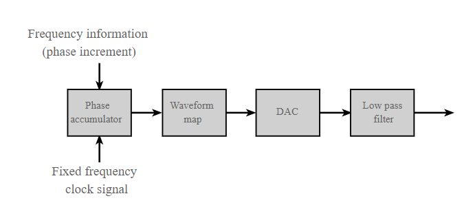
DDS block diagram
Experimental Manuals FII-PRA040 Risc-V

DAC9767 DDS Signal Source Experiment, AD9767 datasheet and use the AD9767 to design a signal source that can generate sine, square, triangle, and sawtooth waves – FII-PRA040 Altera Risc-V Experiment 19

Experiment 19 DAC9767 DDS Signal Source Experiment 19.1 Experiment Objective Learn about DDS (Direct Digital Synthesizer) related theoretical knowledge. Read the AD9767 datasheet and use the AD9767 to design a signal source that can generate sine, square, triangle, and sawtooth waves. 19.2 Experiment Implement Learn about DDS theoretical knowledge. On the basis of understanding the principle of DDS, combined with the theoretical knowledge, use AD9767 module and development board to build a signal source whose waveform, amplitude and frequency can be adjusted. (There are no specific requirements for the adjustment…

Read More
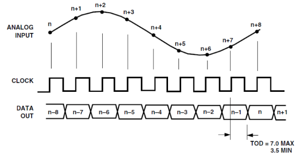
ADC9226 timing diagram
Experimental Manuals FII-PRA040 FPGA Board Based FPGA Tutor Risc-V

High-speed ADC9226 Acquisition Experiment (FII-BD9226) – parallel ADC collectors and master the use of ADC9226 – FII-PRA040 Altera Risc-V Experiment 18

  Experiment 18 High-speed ADC9226 Acquisition Experiment 18.1 Experiment Objective Learn about parallel ADC collectors and master the use of ADC9226. 18.2 Experiment Implement Insert the ADC9226 module face up into the FPGA development board to the GPIO2 and GPIO1 ports which are next to the red-green audio module. Write programs to use this module to test 18.3 Experiment 18.3.1 ADC9226 Module Introduction ADC9226 module adopts AD9226 chip design of ADI Company. This chip is a monolithic, 12-bit, 65 MSPS analog-to-digital converter (ADC). It uses a single power supply and…

Read More