Audio 8978 Loopback Experiment (WM8978 Audio Sub Development Board) , How I2S (Inter-IC Sound) bus work ? – – FII-PRA040 Altera Risc-V Tutorial Experiment 16
Experiment 16 8978 Audio Loopback Experiment
16.1 Experiment Objective
- Learn about I2S (Inter-IC Sound) bus and how it works
- Familiar with the working mode of WM8978. And by configuring the interface mode and selecting the relevant registers in combination with the development board, complete the data transmission and reception, and verify it
16.2 Experiment Implement
- Perform audio loopback test by configuring the onboard audio chip WM8978 to check if the hardware is working properly
- Adjust the volume output level with the keys.
16.3 Experiment
16.3.1 WM8978 Introduction
WM8978 is a low power, high quality stereo multimedia digital signal CODEC introduced by Wolfson. It is mainly used in portable applications such as digital cameras and camcorders. Advanced on-chip digital signal processing includes a 5-band equaliser, a mixed signal Automatic Level Control for the microphone or line input through the ADC as well as a purely digital limiter function for record or playback. Additional digital filtering options are available in the ADC path, to cater for application filtering, such as “wind noise reduction”.
See Figure 16.1 for the internal structure block diagram of WM8978.
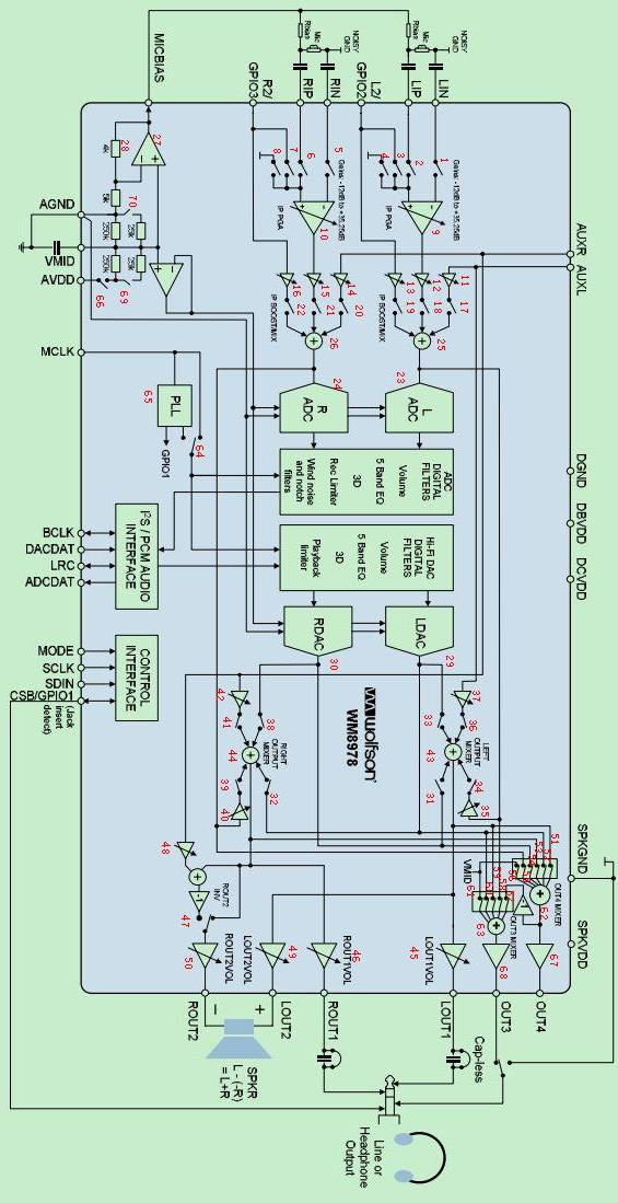
Figure 16.1 WM8978 internal structure block diagram
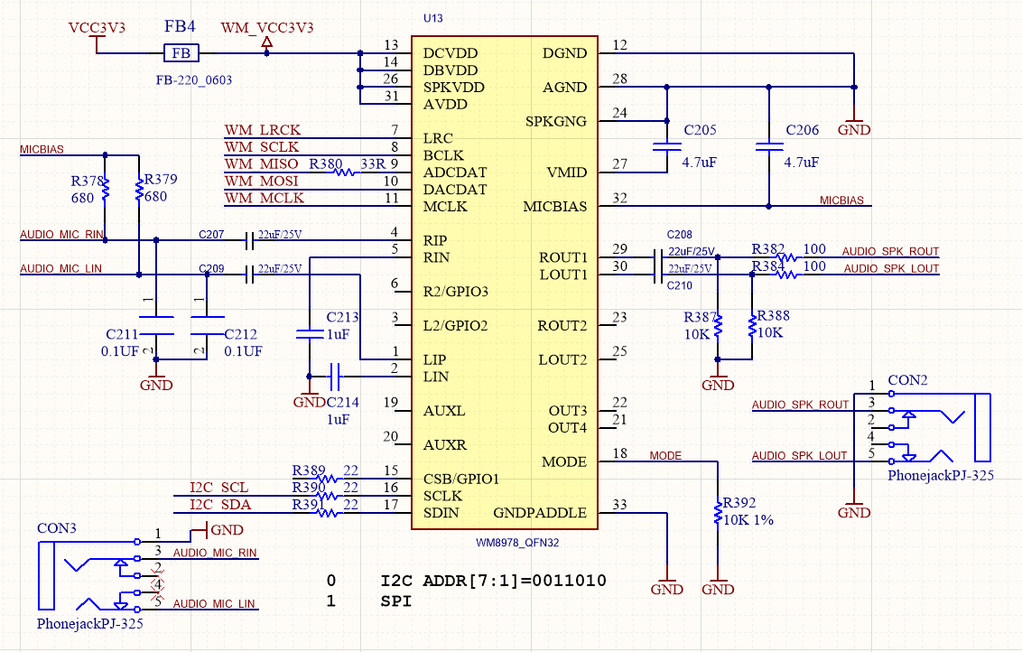
Figure 16.2 Schematics of the audio part of the development board
16.3.2 WM8978 Control Interface Timing
The WM8978 control interface has two-wire mode and three-wire mode. The specific mode is selected by the MODE pin connection of WM8978. When the mode pin is connected to a low voltage level, it is a two-wire mode, and when it is connected to a high voltage level, it is a three-wire mode. The development board mode pin is grounded. When the control interface is in two-wire mode, the timing diagram is shown in Figure 16.3. The timing diagram is the same as the IIC timing. The device address of WM8978 is fixed to 7’b0011010. This chip register only supports writing and does not support reading.
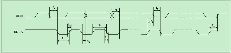
Figure 16.3 Timing diagram of the two-wire mode interface
16.3.3 I2S Audio Bus Protocol
I2S (Inter-IC Sound Bus) is just a branch of PCM, the interface definition is the same, I2S sampling frequency is generally 44.1KHz and 48KHz, PCM sampling frequency is generally 8K, 16K. There are four groups of signals: bit clock signal, synchInter-IC Sound Busronization signal, data input, data output.
I2S is a bus standard developed by Philips for audio data transmission between digital audio devices. In the Philips I2S standard, both the hardware interface specification and the format of digital audio data are specified. I2S has three main signals: the serial clock SCLK, also known as the bit clock BCLK, which corresponds to each bit of data of digital audio. The frequency of SCLK = 2 × sampling frequency × sampling number of bits. The frame clock LRCK is used to switch the data of the left and right channels. An LRCK of “0” indicates that data of the left channel is being transmitted, and “1” indicates that data of the right channel is being transmitted. LRCLK == FS, is the sampling frequency serial data SDATA, which is audio data expressed in two’s complement. Sometimes in order to enable better synchronization between systems, another signal MCLK is needed, which is called the master clock, or also called the system Clock (System Clock). It is 256 or 384 times the sampling frequency.
The timing of the I2S protocol is shown in Figure 16.4. However many bits of data the I2S format signal has, the most significant bit of the data always appears at the second BCLK pulse after the LRCK change (that is, the beginning of a frame). This allows the number of significant digits at the receiving end and the transmitting end to be different. If the receiving end can process less significant bits than the transmitting end, the extra low-order data in the data frame can be discarded; if the receiving end can process more significant bits than the transmitting end, it can make up the remaining bits by itself. This synchronization mechanism makes the interconnection of digital audio equipment more convenient without causing data errors.
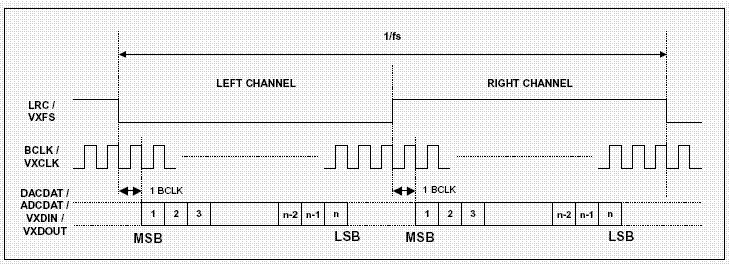
Figure 16.4 I2S timing protocol
16.3.4 Main Program Design
- WM8978 register configuration program
Only the program of register configuration program is given here, please refer to the project file for the complete program
| module wm8978_config
( input clk_50m, output reg cfg_done=0, input rst_n, input rxd, output txd, input key1, input key2, output i2c_sclk, inout i2c_sdat ); wire tr_end; reg [4:0] i; //************************************ reg [23:0] i2c_data_r=0; wire [7:0] data_read ; reg [7:0] read_req ; reg uart_rd =0; reg uart_wr =0; reg [7:0] txd_i2c_data; reg txd_start = 0; wire txd_busy; wire [7:0] rxd_i2c_data; wire rxd_ready; wire rxd_eop; wire test_pin; uart_transceiver uart_transceiver_inst ( .sys_clk (clk_50m), // 50m .uart_rx (rxd), .uart_tx (txd), .divisor (55), // 115200 * 8 .rx_data (rxd_i2c_data), .rx_done (rxd_ready), .rx_eop (rxd_eop), .tx_data (txd_i2c_data), .tx_wr (txd_start), .tx_done (), .tx_busy (txd_busy), .test_pin (), .sys_rst () ); reg rx_end_ack = 0; reg rx_end = 0; always @ (posedge clk_50m) if(rxd_eop) rx_end <= 1; else if(rx_end_ack) rx_end <= 0; reg [7:0] cmd_dir = 0; reg [3:0] uart_st = 0; always @ (posedge clk_50m) if(cfg_done == 0) begin rx_end_ack <= 0; uart_wr <= 0; uart_rd <= 0; uart_st <= 0; end else case(uart_st) 0: begin rx_end_ack <= 0; uart_wr <= 0; uart_rd <= 0; if(rxd_ready) begin cmd_dir <= rxd_i2c_data; uart_st <= 1; end end 1: begin if(rxd_ready) begin i2c_data_r[23:16] <= rxd_i2c_data; uart_st <= 2; end end 2: begin if(rxd_ready) begin i2c_data_r[15:08] <= rxd_i2c_data; if(cmd_dir[0]) uart_st <= 5; else uart_st <= 3; end end 3: // write begin if(rxd_ready) begin i2c_data_r[07:00] <= rxd_i2c_data; uart_wr <= 1; uart_st <= 4; end end 4: begin if(tr_end) begin uart_wr <= 0; uart_st <= 7; end end 5: //read begin uart_rd <= 1; uart_st <= 6; end 6: begin uart_rd <= 0; if(tr_end) begin txd_i2c_data <= data_read; txd_start <= 1; uart_st <= 7; end end 7: begin txd_start <= 0; if(rx_end) begin rx_end_ack <= 1; uart_st <= 0; end else rx_end_ack <= 0; end endcase //*************************************** reg start; //parameter define reg [5:0] PHONE_VOLUME = 6’d32; reg [5:0] SPEAK_VOLUME = 6’d32; reg [31:0] i2c_data=0 ; reg [7:0] start_init_cnt; reg [4:0] init_reg_cnt ; reg [25:0] on_counter; reg [25:0] off_counter; reg key_up, key_down; always @(posedge clk_50m , negedge cfg_done) if (!cfg_done) begin on_counter<=0; off_counter<=0; key_up<=1’b0; key_down<=1’b0; end else begin if (key1==1’b1) on_counter<=0; else if ((key1==1’b0)& (on_counter<=500000)) on_counter<=on_counter+1’b1; if (on_counter==49950) key_up<=1’b1; else key_up<=1’b0; if (key2==1’b1) off_counter<=0; else if ((key2==1’b0)& (off_counter<=500000)) off_counter<=off_counter+1’b1; if (off_counter==49950) key_down<=1’b1; else key_down<=1’b0; end always @(posedge clk_50m , negedge cfg_done) if (!cfg_done) begin PHONE_VOLUME <=6’d32 ; end else begin if (( 2<=PHONE_VOLUME )&( PHONE_VOLUME <=56)&(on_counter==49948)) PHONE_VOLUME <=PHONE_VOLUME+6 ; else if (( 8<=SPEAK_VOLUME )&( SPEAK_VOLUME <=62)& (off_counter==49948)) PHONE_VOLUME <=PHONE_VOLUME-6 ; else PHONE_VOLUME <=PHONE_VOLUME ; end always @ ( posedge clk_50m ) if( rst_n==1’b0 ) begin i <= 5’d0; read_req<=0 ; i2c_data <= 32’h000000; start <= 1’b0; cfg_done <=0; end else begin case( i ) 0: begin if( tr_end ) begin start <= 1’b00; i <= i + 1’b1; end else begin start <= 1’b1; i2c_data <= {7’h1a,1’b0,8’h00,7’d0 ,9’b1}; end end 1: begin if( tr_end ) begin start <= 1’b0; i <= i + 1’b1; end else begin start <= 1’b1; i2c_data <={7’h1a,1’b0, 8’h00,7’d1 ,9’b1_0010_1111}; end end 2: begin if( tr_end ) begin start <= 1’b0; i <= i + 1’b1; end else begin start <= 1’b1; i2c_data <= {7’h1a,1’b0,8’h00,7’d2 ,9’b1_1011_0011}; end end 3: begin if( tr_end ) begin start <= 1’b0; i <= i + 1’b1; end else begin start <= 1’b1; i2c_data <= {7’h1a,1’b0,8’h00,7’d3 ,9’b0_0110_1111}; end end 4: begin if( tr_end ) begin start <= 1’b0; i <= i + 1’b1; end else begin start <= 1’b1; i2c_data <= {7’h1a,1’b0,8’h00,7’d4 ,{2’d0,2’b11,5’b10000}}; end end 5: begin if( tr_end ) begin start <= 1’b0; i <= i + 1’b1; end else begin start <= 1’b1; i2c_data <={7’h1a,1’b0,8’h00,7’d6 ,9’b0_0000_0001}; end end 6: begin if( tr_end ) begin start <= 2’b00; i <= i + 1’b1; end else begin start <= 1’b1; i2c_data<= {7’h1a,1’b0,8’h00,7’d7 ,9’b0_0000_0001}; end end 7: begin if( tr_end ) begin start <= 1’b0; i <= i + 1’b1; end else begin start <= 1’b1; i2c_data <= {7’h1a,1’b0,8’h00,7’d10,9’b0_0000_1000}; end end 8: begin if( tr_end ) begin start <= 1’b0; i <= i + 1’b1; end else begin start <= 1’b1; i2c_data <= {7’h1a,1’b0,8’h00,7’d14,9’b1_0000_1000}; end end 9: begin if( tr_end ) begin start <= 1’b0; i <= i + 1’b1; end else begin start <= 1’b1; i2c_data <= {7’h1a,1’b0,8’h00,7’d43,9’b0_0001_0000}; end end 10: begin if( tr_end ) begin start <= 1’b0; i <= i + 1’b1; end else begin start <= 1’b1; i2c_data <={7’h1a,1’b0,8’h00,7’d47,9’b0_0111_0000}; end end 11: begin if( tr_end ) begin start <= 1’b0; i <= i + 1’b1; end else begin start <= 1’b1; i2c_data <={7’h1a,1’b0,8’h00,7’d48,9’b0_0111_0000}; end end 12: begin if( tr_end ) begin start <= 1’b0; i <= i + 1’b1; end else begin start <= 1’b1; i2c_data <={7’h1a,1’b0,8’h00,7’d49,9’b0_0000_0110}; end end 13: begin if( tr_end ) begin start <= 1’b0; i <= i + 1’b1; end else begin start <= 1’b1; i2c_data <= {7’h1a,1’b0,8’h00,7’d50,9’b1 };end end 14: begin if( tr_end ) begin start <= 1’b0; i <= i + 1’b1; end else begin start <= 1’b1; i2c_data <= {7’h1a,1’b0,8’h00,7’d51,9’b1 };end end 15: begin if( tr_end ) begin start <= 1’b0; i <= i + 1’b1; end else begin start <= 1’b1; i2c_data <={7’h1a,1’b0,8’h00,7’d52,{3’b010,PHONE_VOLUME}};end end 16: begin if( tr_end ) begin start <= 1’b0; i <= i + 1; end else begin start <= 1’b1; i2c_data <= {7’h1a,1’b0,8’h00,7’d53,{3’b110,PHONE_VOLUME}};end end 17: begin cfg_done<=1 ; if (uart_wr) begin start <= 1’b1; i2c_data <={cmd_dir,i2c_data_r} ; i<=i+1 ; end if (uart_rd) begin read_req <= 1’b1; i2c_data <={cmd_dir,i2c_data_r} ; i<=i+2 ; end if (key_up|key_down) i<= 15; end 18: begin if( tr_end ) begin start <= 1’b0; i <=19; end else i<=20; end 19: begin if( tr_end ) begin read_req <= 1’b0; i <= 19; end else begin i<=21;end end default:i<=1 ; endcase end i2c_control i2c_control_inst ( .Clk (clk_50m), .Rst_n(rst_n), .wrreg_req(start) , .rdreg_req (read_req), .addr({i2c_data[15:8],i2c_data[23:16]}) , //16bit .addr_mode(0), .wrdata (i2c_data[7:0]), // .rddata (data_read), //8bit .device_id (i2c_data[31:24]), //8bit .RW_Done(tr_end), .ack (), .i2c_sclk(i2c_sclk), .i2c_sdat(i2c_sdat) ); endmodule |
- Audio signal acquisition program
| module audio_receive (
//system clock 50MHz input rst_n , //wm8978 interface input aud_bclk , input aud_lrc , input aud_adcdat, //user interface output reg rx_done , output reg [31:0] adc_data ); parameter WL = 6’d32 ; reg aud_lrc_d0; reg [ 5:0] rx_cnt; reg [31:0] adc_data_t; wire lrc_edge ; assign lrc_edge = aud_lrc ^ aud_lrc_d0; always @(posedge aud_bclk or negedge rst_n) begin if(!rst_n) aud_lrc_d0 <= 1’b0; else aud_lrc_d0 <= aud_lrc; end always @(posedge aud_bclk or negedge rst_n) begin if(!rst_n) begin rx_cnt <= 6’d0; end else if(lrc_edge == 1’b1) rx_cnt <= 6’d0; else if(rx_cnt < 6’d35) rx_cnt <= rx_cnt + 1’b1; end always @(posedge aud_bclk or negedge rst_n) begin if(!rst_n) begin adc_data_t <= 32’b0; end else if(rx_cnt < WL) adc_data_t[WL – 1’d1 – rx_cnt] <= aud_adcdat; always @(posedge aud_bclk or negedge rst_n) begin if(!rst_n) begin rx_done <= 1’b0; adc_data <= 32’b0; end else if(rx_cnt == 6’d32) begin rx_done <= 1’b1; adc_data<= adc_data_t; end else rx_done <= 1’b0; end endmodule |
- Audio sending module
| module audio_send (
input rst_n , input aud_bclk , input aud_lrc , output reg aud_dacdat, input [31:0] dac_data , output reg tx_done ); parameter WL = 6’d32 ; reg aud_lrc_d0; reg [ 5:0] tx_cnt; reg [31:0] dac_data_t; wire lrc_edge; assign lrc_edge = aud_lrc ^ aud_lrc_d0; always @(posedge aud_bclk or negedge rst_n) begin if(!rst_n) aud_lrc_d0 <= 1’b0; else aud_lrc_d0 <= aud_lrc; end always @(posedge aud_bclk or negedge rst_n) begin if(!rst_n) begin tx_cnt <= 6’d0; dac_data_t <= 32’d0; end else if(lrc_edge == 1’b1) begin tx_cnt <= 6’d0; dac_data_t <= dac_data; end else if(tx_cnt < 6’d35) tx_cnt <= tx_cnt + 1’b1; end always @(posedge aud_bclk or negedge rst_n) begin if(!rst_n) begin tx_done <= 1’b0; end else if(tx_cnt == 6’d32) tx_done <= 1’b1; else tx_done <= 1’b0; end always @(negedge aud_bclk or negedge rst_n) begin if(!rst_n) begin aud_dacdat <= 1’b0; end else if(tx_cnt < WL) aud_dacdat <= dac_data_t[WL – 1’d1 – tx_cnt]; else aud_dacdat <= 1’b0; end endmodule |
- Main program
| module audio_test(
input wire sys_clk_50, input wire rst_n, input rxd, output txd, output [7:0] led , input key1, input key2, inout wm_sdin, output wm_sclk, input wire wm_lrc, input wire wm_bclk, input wire adcdat, output wire dacdat, output wire mclk ); wire cfg_done ; assign led ={7’h7f,~cfg_done} ; pll_50_12 pll_50_12_inst ( // Clock out ports .c0(clk_out_12), // output clk_out_12 // Status and control signals .areset(~rst_n), // input reset .locked(locked), // output locked // Clock in ports .inclk0(sys_clk_50)); // input sys_clk_50 wire clk_out_12 ; assign mclk = clk_out_12 ; wm8978_config wm8978_config_inst ( .key1 (key1), .key2 (key2), .clk_50m (sys_clk_50 ) , .rst_n (rst_n) , .cfg_done (cfg_done) , .i2c_sclk (wm_sclk) , .rxd (rxd), .txd (txd), .i2c_sdat (wm_sdin) ); wire [31:0] adc_data ; audio_receive audio_receive_inst( .rst_n (rst_n), .aud_bclk (wm_bclk), .aud_lrc (wm_lrc), .aud_adcdat (adcdat), .adc_data (adc_data), .rx_done (rx_done) ); audio_send audio_send_inst( .rst_n (rst_n), .aud_bclk (wm_bclk), .aud_lrc (wm_lrc), .aud_dacdat (dacdat), .dac_data (adc_data), .tx_done (tx_done) ); endmodule |
16.4 Experiment Verification
- Pin assignment
Table 16.1 Pin assignment
| Signal Name | Port Description | Network Label | FPGA Pin |
| Sys_clk_50 | System 50M clock | C10_50MCLK | G21 |
| Reset_n | System reset signal | KEY1 | Y4 |
| Wm_sdin | 8978 register configuration data line | I2C_SDA | C13 |
| Wm_sclk | 8978 register configuration clock | I2C_SCL | D13 |
| Wm_lrc | 8978 align clock | WM_LRCK | AB19 |
| Wm_bclk | 8978 bit clock | WM_BCLK | AA19 |
| adcdat | ADC input of 8978 | WM_MISO | AA18 |
| Dacdat | DAC input of 8978 | WM_MOSI | Y17 |
| Mack | PLL provides 8978 working master clock | WM_MCLK | W17 |
| Key1 | Volume up button | Key2 | V5 |
| Key2 | Volume down button | Key7 | AB3 |
| txd | Serial transmit | TTL_RX | E16 |
| rxd | Serial receive | TTL_TX | F15 |
- Board verification
As shown in Figure 16.5 below, after the FPGA development board is programmed, use a dual male audio cable, with one end plugged into the red audio receiver end and the other end plugged into a music player. Plug the headphone into the green audio playback port. The music can be heard from player. The volume is divided into 5 gears. Press the UP key to increase the volume and press the down key to decrease the volume.
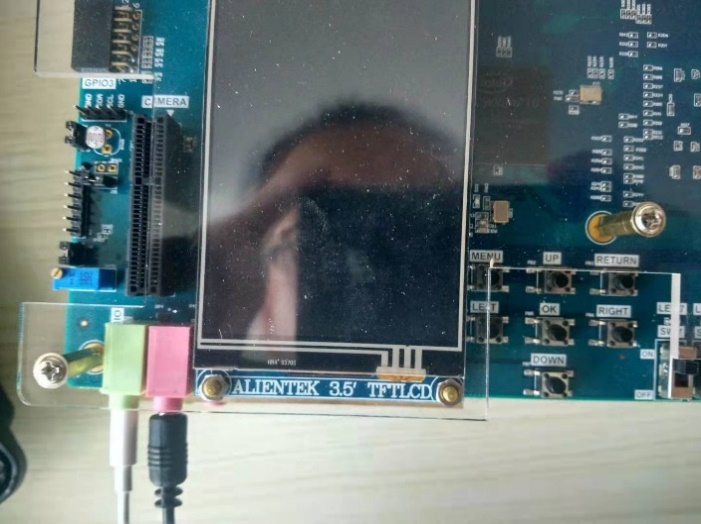
Figure 16.5 wm8978 board verification