C Programming (1) on RISCV FII-PRX100 (ARTIX-7, XC7A100T) XILINX FPGA Board with our FII-Risc-V CPU (RV32G2.0)
V1.0
Fraser Innovation inc
RISCV FII-PRX100 (ARTIX-7, XC7A100T) XILINX FPGA Board C Programming 1
Version Control
| Version | Date | Description |
| 1.0 | 10/24/2020 | Initial Release |
Copyright Notice:
© 2020 Fraser Innovation Inc ALL RIGHTS RESERVED
Without written permission of Fraser Innovation Inc, no unit or individual may extract or modify part of or all the contents of this manual. Offenders will be held liable for their legal responsibility.
Thank you for purchasing the FPGA development board. Please read the manual carefully before using the product and make sure that you know how to use the product correctly. Improper operation may damage the development board. This manual is constantly updated, and it is recommended that you download the latest version when using.
Official Shopping Website:
https://fpgamarketing.com/FII-PRX100-D-ARTIX-100T-XC7A100T-RISC-V-FPGA-Board-PRX100-D-1.htm
Content
1. Introduction to FII-RISCV CPU 4
2. RISCV FII-PRX100 (ARTIX-7, XC7A100T) Xilinx FPGA Board 9
3. C Project Compilation Process 11
4. Using Freedom Studio to Create a New C Project 14
5. C Project Files Composition 30
6. Exercise 37
7. References 38
Introduction to FII-RISCV CPU
First of all, there is an overview of the CPU, FII-RISCV. RISCV is an open standard instruction set architecture (ISA) based on reduced instruction set computer (RISC) principles [1]. FII-RISCV is researched and developed following the RISCV standard. Here are some basic features about FII-RISCV:
- RV32I (32 registers that supports integer operations)
- Does not support multiplication instructions (the newest version do support)
- Does not support Atomic operations
- Does not support compressed instruction
- Supports software interrupt
- Supports timer interrupt
- Supports UART output (Peripherals)
- Supports 4 groups of GPIO interfaces (32 pins per group)
- 4K bytes DTCM
- 16K bytes ITCM
Here is a screenshot of the address allocation, which is helpful when writing the C project, as shown in Figure 1.
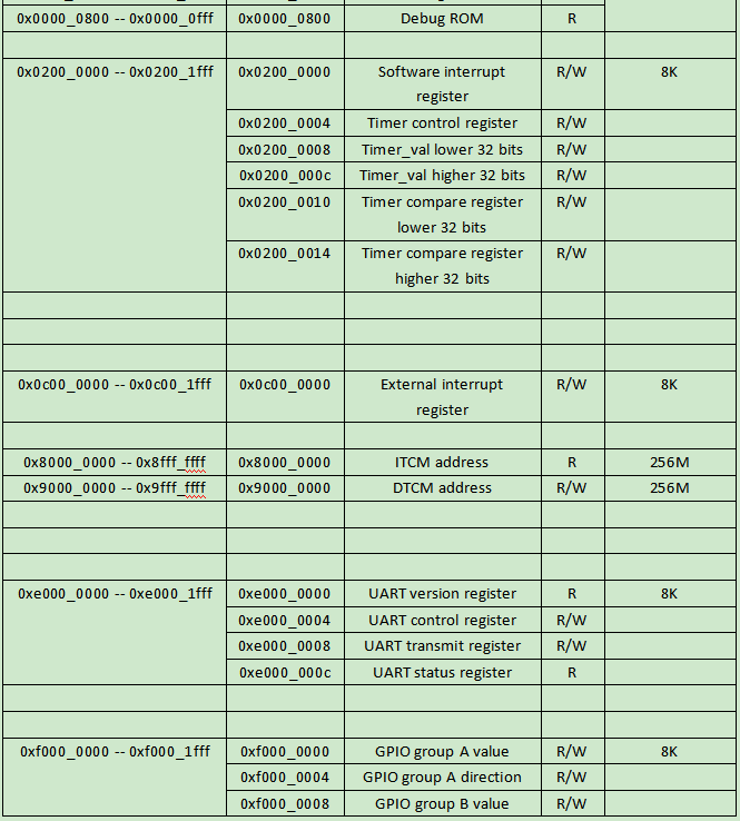
Figure 1 Address allocation
The GPIO configuration is shown below. The relevant code block is located in the top level entity, fii_cpu_sys.v.
wire [ 31: 0 ] gpio_ia;
wire [ 31: 0 ] gpio_oa;
wire [ 31: 0 ] gpio_ta;
wire [ 31: 0 ] gpio_a;
//IO buffer for LED
fii_iobuf #( .IO_WIDTH( 32 ) )
fii_iobuf_insta
(
.i_dio_t ( gpio_ta ),
.i_dio ( gpio_oa ),
.o_dio ( gpio_ia ),
.io_dio_p ( gpio_a )
);
assign LED = gpio_a[ IO_WIDTHa – 1: 0 ];
wire [ 31: 0 ] gpio_ib;
wire [ 31: 0 ] gpio_ob;
wire [ 31: 0 ] gpio_tb;
wire [ 31: 0 ] gpio_b;
//IO buffer for segment display location selection
fii_iobuf #( .IO_WIDTH( 32 ) )
fii_iobuf_instb
(
.i_dio_t ( gpio_tb ),
.i_dio ( gpio_ob ),
.o_dio ( gpio_ib ),
.io_dio_p ( gpio_b )
);
assign SEAT = gpio_b[ IO_WIDTHb – 1: 0 ];
wire [ 31: 0 ] gpio_ic;
wire [ 31: 0 ] gpio_oc;
wire [ 31: 0 ] gpio_tc;
wire [ 31: 0 ] gpio_c;
//IO buffer for segment selection
fii_iobuf #( .IO_WIDTH( 32 ) )
fii_iobuf_instc
(
.i_dio_t ( gpio_tc ),
.i_dio ( gpio_oc ),
.o_dio ( gpio_ic ),
.io_dio_p ( gpio_c )
);
assign SEG = gpio_c[ IO_WIDTHc – 1: 0 ];
wire [ 31: 0 ] gpio_id;
wire [ 31: 0 ] gpio_od;
wire [ 31: 0 ] gpio_td;
wire [ 31: 0 ] gpio_d;
//IO buffer fro push buttons
fii_iobuf #( .IO_WIDTH( 32 ) )
fii_iobuf_instd
(
.i_dio_t ( gpio_td ),
.i_dio ( gpio_od ),
.o_dio ( gpio_id ),
.io_dio_p ( gpio_d )
);
assign PB = gpio_d[2:0];
It’s important to note that only when using “assign” with I/O buffer, “assign” can connect an inout type, otherwise, “assign” always connects an output.
RISCV FII-PRX100 (ARTIX-7, XC7A100T) Xilinx FPGA Board
RISCV FII-PRX100 Xilinx FPGA board has two versions, one has SRAM, denotes as PRX100-S, the other has DDR instead of SRAM, denotes as PRX100-D (https://fpgamarketing.com/FII-PRX100-D-ARTIX-100T-XC7A100T-RISC-V-FPGA-Board-PRX100-D-1.htm). See Figure 2 and 3 for different versions of PRX100. The difference could be easily found by observing the highlighted area on board. DDR version has an obvious IC on the front marked as “DDR”.
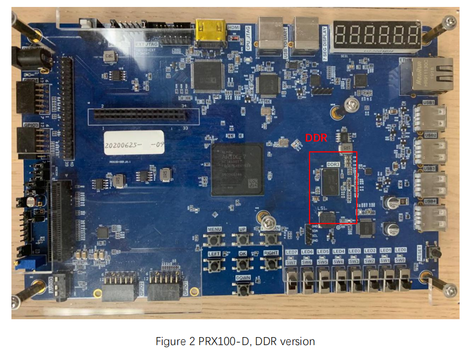
Figure 2 PRX100-D, DDR version
Take PRX100-S as an example, the two interfaces, JTAG and UART have been highlighted in Figure 3. Note to connect jumper J6 1-2 to use J4 or J5 as external download interface as shown in Figure 4. JTAG interface is used to program FPGA. UART interface is used to output to the computer. Before using Freedom Studio to run the C program, the FPGA board needs to be programmed with RISCV verilog project.
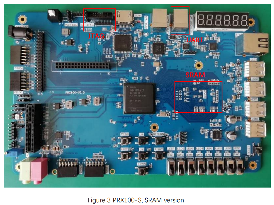
Figure 3 PRX100-S, SRAM version
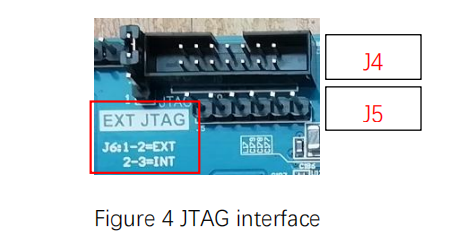
Figure 4 JTAG interface
C Project Compilation Process
As shown in Figure 5, the translation procedure for C program is as follows:
- Write C source code (e.g. foo.c in Unix and MS-DOS)
- Compiler converts C program to assembly program (e.g. foo.s in Unix, foo.asm in MS-DOS )
- Assembler converts assembly program to the machine language module (object, e.g. foo.o in Unix, foo.obj in MS-DOS)
- Linker assembles machine language module, including libraries to the executable file (e.g. a.out in Unix, a.exe in MS-DOS)
- At run time, loader would load the program into memory and jump to the address where it started.
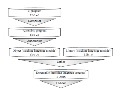
Figure 5 Translate the C source code to runnable program [2]
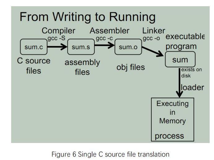
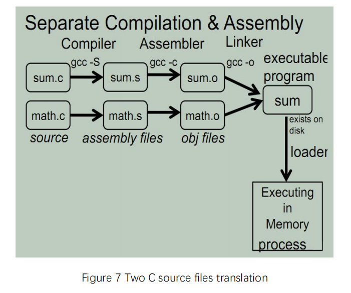
The following figures 6-8 illustrate different translation situations. It can be seen that the compiler and assembler translate the C source files to the object files, where the linker links every object files together when translating multiple files. If only the assembly files or object files are given, then the compiler or assembler translation could be neglected.
![]()
Figure 8 Multiple types of files (*.c, *.s, *.o) translation
Using Freedom Studio to Create a New C Project
Here, Freedom Studio is used as the development platform. It is based on the industry standard Eclipse IDE, and is compatible with RISCV hardware boards by SiFive company[3]. Besides, it has prebuilt RISCV GCC toolchain and emulator.
Follow the steps shown below to create a new C project in Freedom Studio.
Firstly, go to File > New > C Project, then a window will pop up as shown in Figure 10. Set the Project name to be test. For the Project type, choose Empty Project, and the Toolchains choose RISC-V Cross GCC. The other settings will remain default. Click two time Next and then Finish the setting.
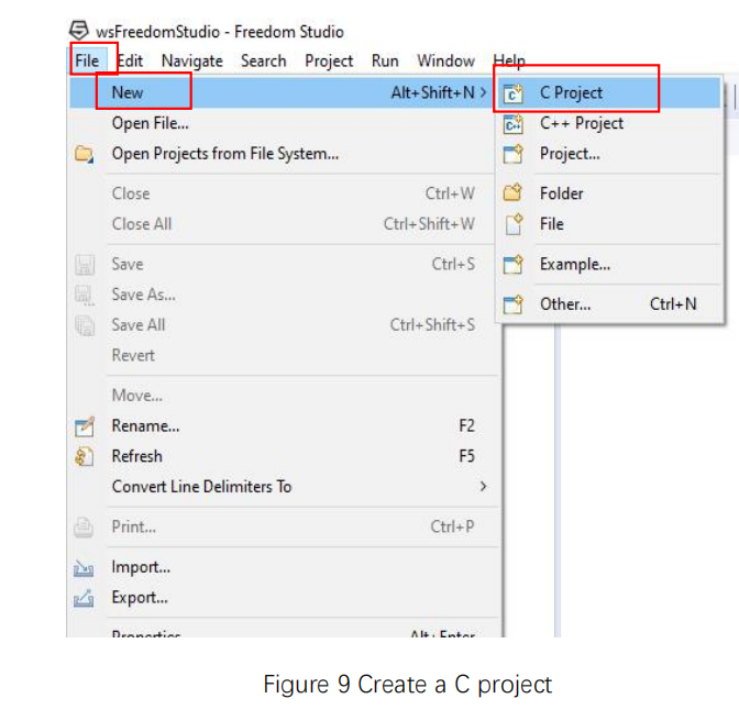
Figure 9 Create a C project
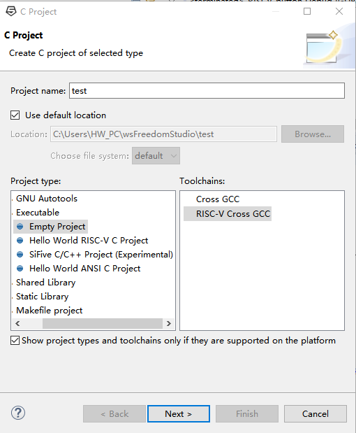
Figure 10 C project setup
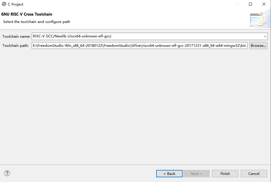
Figure 11 Finish the new C project setting
Right click the new created C project, and select Properties as shown in Figure 12, a window in Figure 13 will pop up.
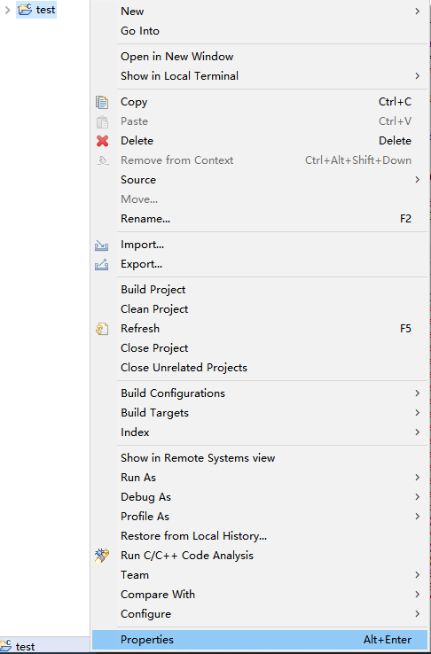
Figure 12 Project properties
There are lots of items in Figure 13 needed to be notified. To enter the general setting interface, click Settings under C/C++ Build drop-down menu in the left column, then the corresponding setting will occur in the right part.
Firstly, click the Target Processor. Since FII RISCV is 32bit, integer-based instruction set, choose RV32I (-march=rv32i*) for Architecture. Note do not check the Multiple extension or Atomic extension below. For Integer ABI, choose ILP32 (-mabi=ilp32*). ABI (application binary interface) is a format defines the data structure and computational routines. ILP32 means int type, long type, and the pointer type in C project are all 32 bits. For small data limit, fill 4.
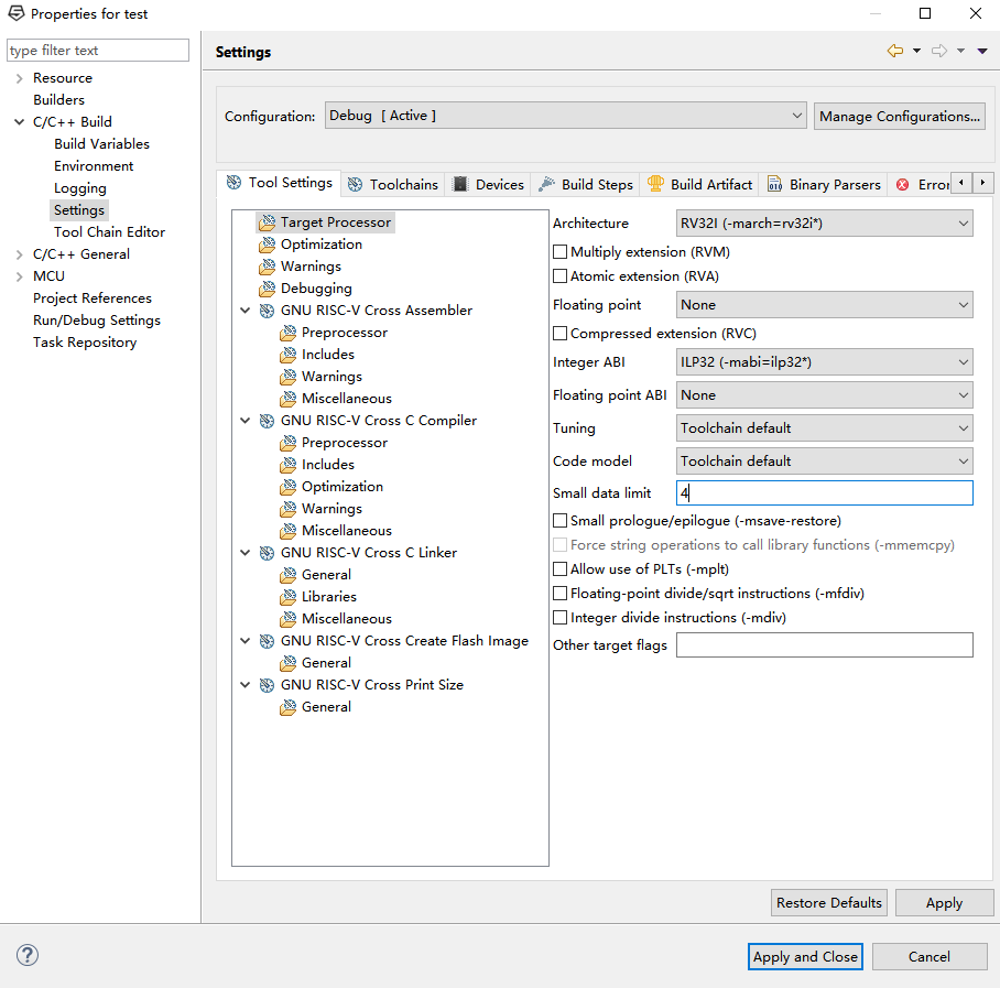
Figure 13 Target Processor setting
In Figure 14, for Optimization setting, choose Optimize for debug (-Og) for the Optimization Level. Check Disable builtin (-fno-builtin) to disable all replacement and inlining of standard C library functions with equivalents. The other checkboxes will remain default.
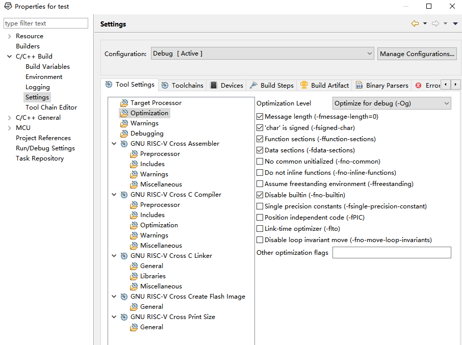
Figure 14 Optimization setting
In Figure 15, click Warnings, and click Enable all common warnings (-Wall). This option will provide common warning information. It is useful since fixing common warning will prevent the occurrence of critical errors.
Click Debugging to enter the debugging setting as shown in Figure 16. Set the Debug level to be Default (-g).
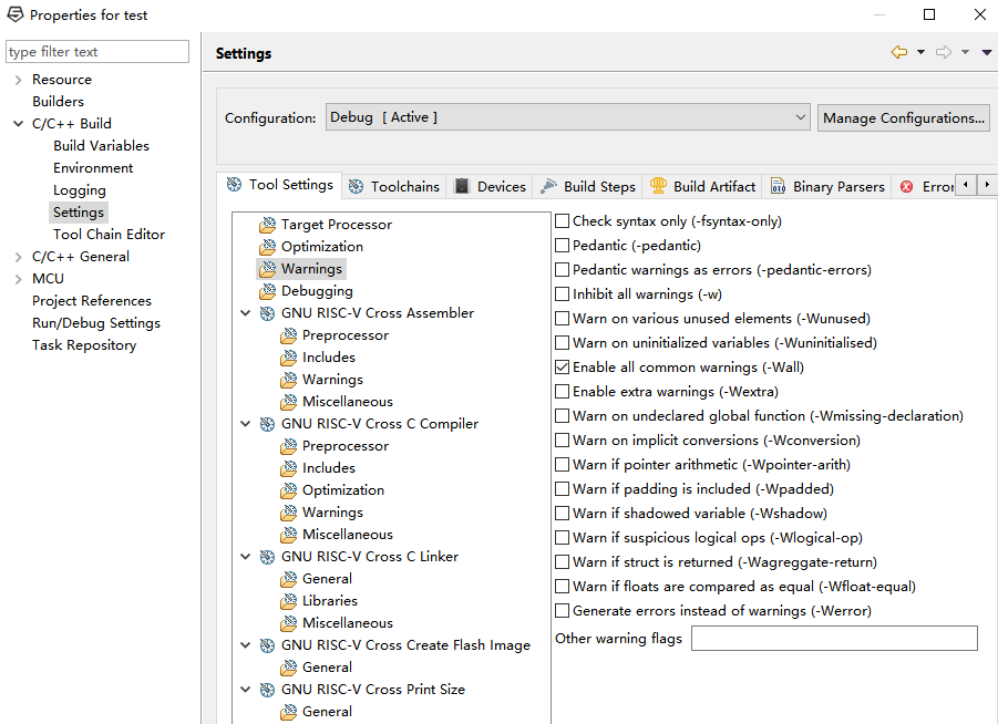
Figure 15 Warning setting
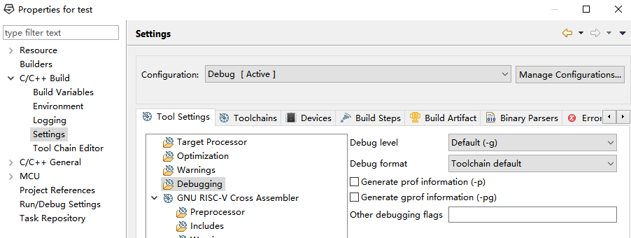
Figure 16 Debugging setting
Find General under GNU RISC-V Cross Linker, and check Do not use standard start files (-nostartfiles) as shown in Figure 17. A customized start file will be used, and will be introduced later.
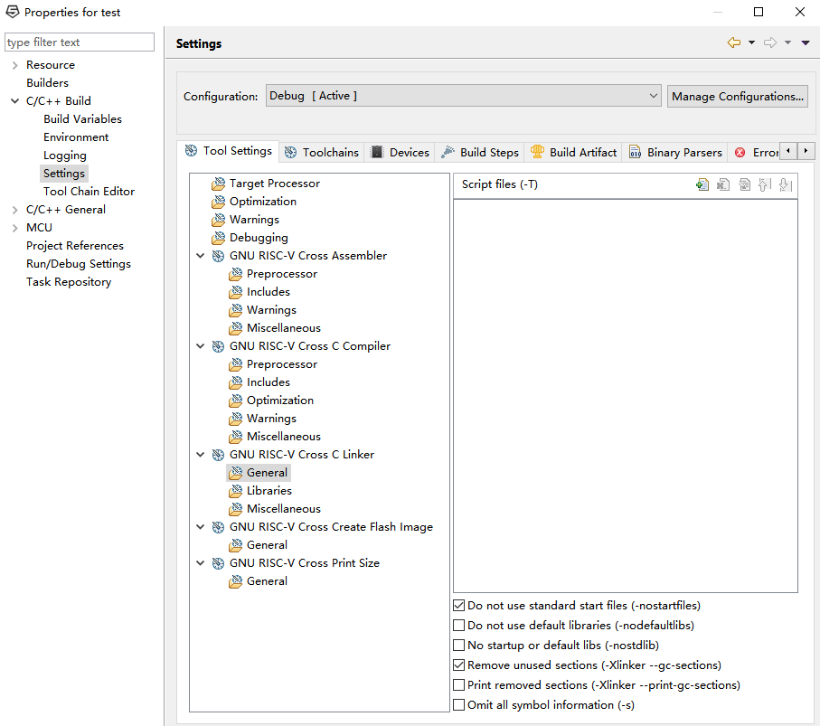
Figure 17 Linker general setting
In Miscellaneous setting under GNU RISC-V Cross C Linker as shown in Figure 18, check Use newlib-nano (–specs=nano.specs), and set Other linker flags to be -t -nostdinc –entry _start -Wl, -m, elf32lriscv -Wl, -EL, -b, elf32-littleriscv -Wl, –check-sections -Wl, –wrap=printf. See Table 1 for the detailed option explanations. Other options could be found available on GNC official website.
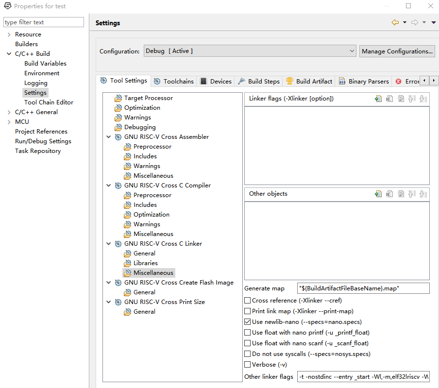
Figure 18 Miscellaneous setting
| Option | Description |
| –specs=nano.specs | Add newlib-nano, nano is designed for small embedded applications |
| -t | Trace file opens |
| -nostdinc | Do not search the standard system directories for header files |
| –entry _start | Set start address as startup.s |
| -Wl | Pass the option behind to the linker |
| -m | Set emulation |
| Elf32lriscv | Output file in RISCV32I format |
| -El | Link little-endian objects |
| -b | Specify target for following input files |
| Elf32-littleriscv | Output file in little-endian format |
| –check-sections | Check section addresses for overlaps |
| –wrap=printf | Use wrapper function for printf |
Table 1 Linker option explanation
In Figure 19, choose Raw binary for General setting under GNU RISC-V Cross Create Flash Image. This option outputs raw binary file, which can be used to program the FLASH.
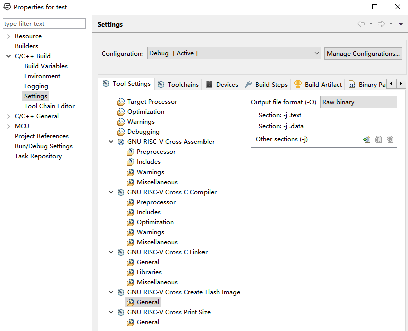
Figure 19 Flash Image setting
Next, start to configure the new C project with some existing files from RISCV_Hello. Select bsp, inc, entry.S, main.S, startup.S, sys.lds, and test_dbg.cfg files, right click to select Copy on the popup menu, and then right click test project, select Paste to paste all copied files. The procedure is shown in Figure 20 -21.
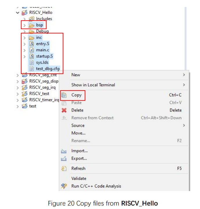
Figure 20 Copy files from RISCV_Hello
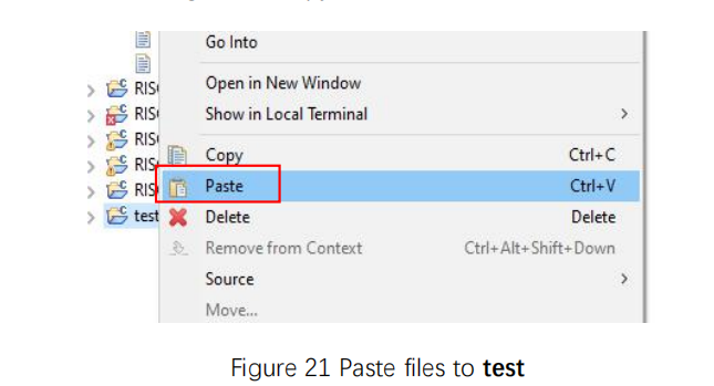
Figure 21 Paste files to test
After adding the files to the test project, right click it, and select Properties as shown in Figure 12 as before. In Figure 22, click Includes setting under GNU RISC-V Cross C Compiler. In the Include paths, click the Add icon, then a popup window will show up. In the Directory column, fill ${workspace_loc:/${ProjName}/inc} or select Workspace, and choose inc under test project as shown in Figure 23. Click OK to finish.
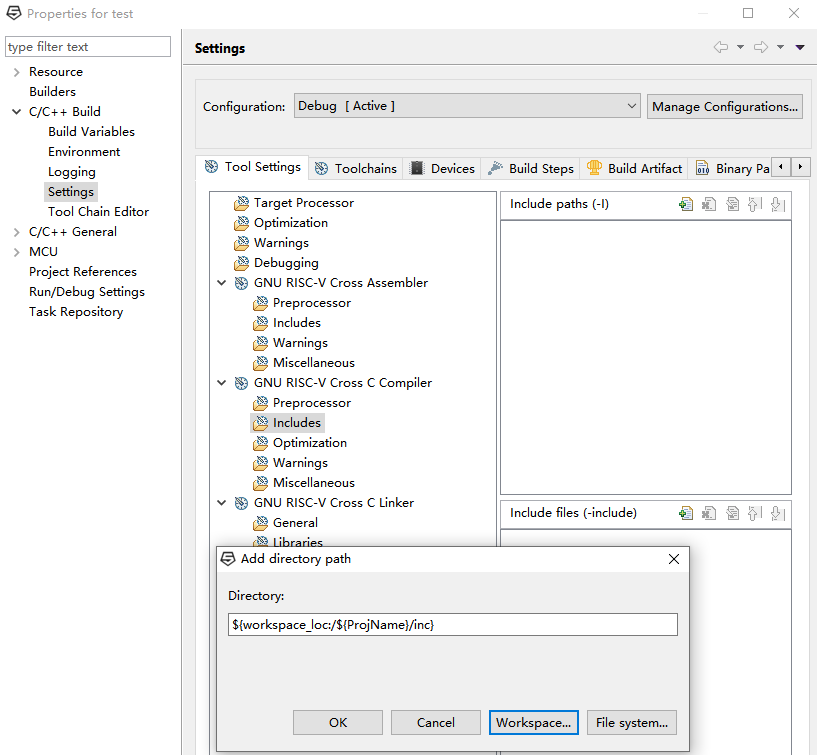
Figure 22 Include the header files
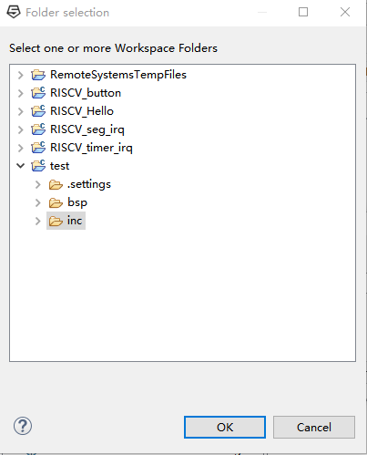
Figure 23 Add directory path
In Figure 24, click General setting of GNU RISC-V Cross C Linker, in the right Script files, click Add icon to add path to the linker script. Fill ${workspace_loc:/${ProjName}/sys.lds} to the File , or click Workspace, and find the sys.lds under test project shown in Figure 25. Then click Apply and Close to finish the setting.
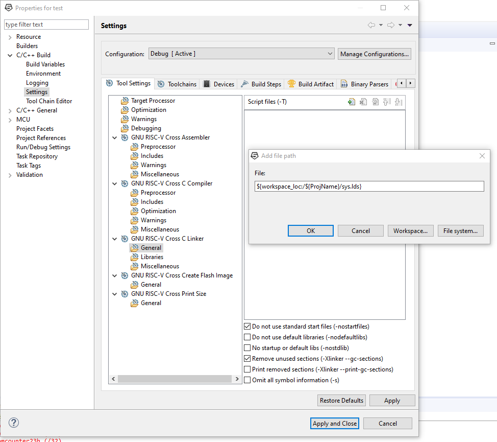
Figure 24 Include the linker script
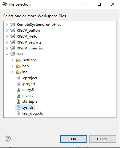
Figure 25 Add file path
After all of the the previous steps have been done, Clean Project, Build Project, and Refresh as shown in Figure 26.
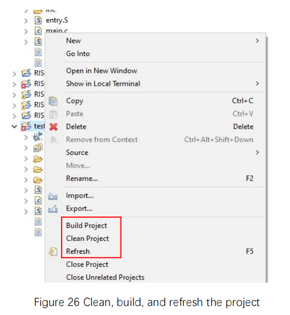
Figure 26 Clean, build, and refresh the project
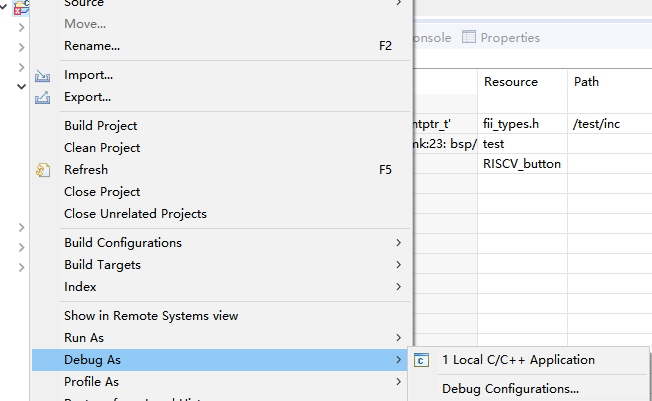
Figure 27 Debug
Right click test project and select Debug As > Debug Configurations as shown in Figure 27. Figure 28 shows the debug configuration popup window. Under GDB OpenOCD Debugging, click the upper left corner icon, New launch configuration to add test Debug. Usually after building projects, with refresh, the C/C++ Application row under the Main tab will fill up the corresponding *.elf file automatically. If not, click Search Project under the blank, to search for the *.elf file. Or else, use Browse button to find the *.elf file under debug folder (this will be an absolute path).
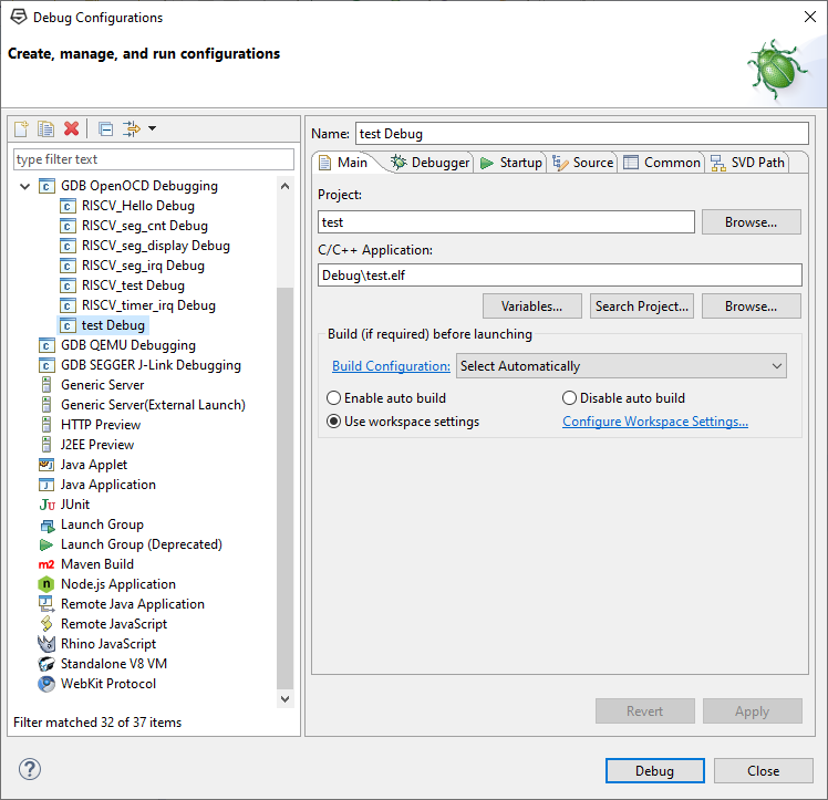
Figure 28 Debug configurations
Figure 29 shows the Debugger setting. Fill -f test_dbg.cfg in Config options, and fill set mem inaccessible-by-default off in Commands. Then click Debug to start debugging. “set mem inaccessible-by-default off” makes GDB treat the memory not explicitly described by the memory range as RAM [4].
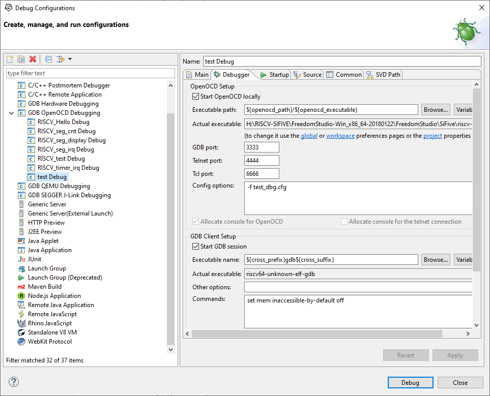
Figure 29 Debugger setting
C Project Files Composition
- Test_dbg.cfg
It is mainly used to configure OpenOCD, and is not required for the normal project, only used for debugging. Generally, users do not need to modify it. It mainly includes jtag adapter interface clock configuration, jtag adapter interface chip configuration, CPU type, information of jtag module, and etc..
- Entry.S
It is not used here, but will be used for interrupt project later. Detailed introduction will be present in C programming 2.
- Startup.S
The first ever file will be executed in the project. It is assigned to the initial address space by the sys.lds file.
The main purpose is to initialize the registers, including the 31 registers ( X0 is hardwired to 0) and CSR registers. It also sets the stack initial position and call main function of the C source file.
- Sys.lds
It is used to sort and classified store different file and variables under uniform address coding. See Figure 30 for a general idea of linker functionality. The code block is attached as well, and the detailed explanation is commended inside the code block.
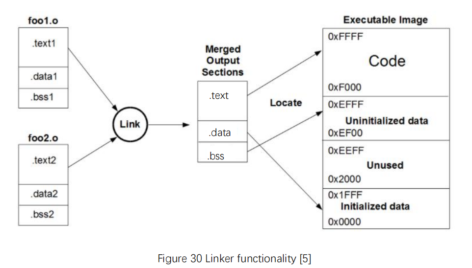
Figure 30 Linker functionality [5]
OUTPUT_FORMAT( “elf32-littleriscv” )/* specify the output as executable and linking format -> *.elf , and in 32 bits little endian*/
OUTPUT_ARCH( “riscv” )/*specify the output architecture is RISCV */
OUTPUT( “asm_temp.bin” )/* specify the output file is asm_temp.bin, function the same as -o filename in the command line, if setting both at the same time, the command line has priority */
ENTRY(_start)/*set the start address as startup.s, function the same as –entry _filename in the command line
if setting both at the same time, the command line has priority */
_STACK_SIZE = 0x100;/*define a macro */
_HEAP_SIZE = 0x400;/*define a macro */
/*MEMORY: describe a memory block location and size
syntax:
MEMORY
{
name [(attr)] : ORIGIN = origin, LENGTH = len
…
}
attr must consist only of the following characters:
R: read-only section
W: read/write section
X: executable section
A: allocatable section
I: initialized section
L: same as ‘I’
!: Invert the sense of any of the attributes that follow
origin is the start address of the memory region, it must evaluate to a constant and it cannot involve any symbols
len is an expression for the size in bytes of the memory region
*/
MEMORY
{
rom (rx) : ORIGIN = 0x80000000, LENGTH = 32K
ram (wx!r) : ORIGIN = 0x90000000, LENGTH = 4K
}
SECTIONS/*section command */
{
. = 0x80000000; /*.address is set as 0x80000000 */
.init :/*initialization section */
{
KEEP (*(SORT_NONE(.init)))/* put .init content into initialization, SORT_NONE means keeping the order*/
}
.text :/* program code*/
{
*(.text)/*put all the program code here */
}
.rodata : /*read-only data*/
{
*(.rodata) /* put all the read-only data here*/
}
. = 0x90000000;/*.address is set as 0x90000000 */
.data : /* read-write initialized data*/
{
*(.data) /* put all the read-write initialized data here*/
}
.bss : /* read-write zero initialized data*/
{
. = ALIGN(4);/* align with 4 bytes */
*(.bss)/* put all the read-write zero initialized data here*/
*(COMMON)/* put all the common symbols here*/
. = ALIGN(4);/*align with 4 bytes */
__bss_end = .;/*assign __bss_end as the current address */
}
. = ALIGN(16);/* align with 16 bytes*/
.heap : /*define heap section */
{
_heap_begin = .;/*define _heap_begin address*/
_heap_start = .;/*define _heap_start address*/
. = . + _HEAP_SIZE;/*define heap size*/
. = ALIGN(16);/*align with 16 bytes*/
_heap_end = .;/*define _heap_end address*/
}
. = ALIGN(8);/*align with 8 bytes */
/*provide is to define a symbol only if it is referenced and is not defined by any object included*/
PROVIDE( _end = . );/*define _end address */
PROVIDE( end = . );/*define end address */
.stack ORIGIN(ram) + LENGTH(ram) – _STACK_SIZE :/*define .stack address */
{
. = _STACK_SIZE;/*_STACK_SIZE assign the address*/
PROVIDE( _sp = . );/*define _sp address */
}
}
- Extra note
Right click test project, and go to Properties > Settings > Build Steps, as shown in Figure 31. Fill riscv64-unknown-elf-objdump.exe ${ProjName}.elf -d –full-contents -M no-aliases > fii.txt in the Post-build steps Command column, and compare with the result got when filling riscv64-unknown-elf-objdump.exe ${ProjName}.elf -d –full-contents -M no-aliases,numeric > fii.txt. See Table 2 for flag details.
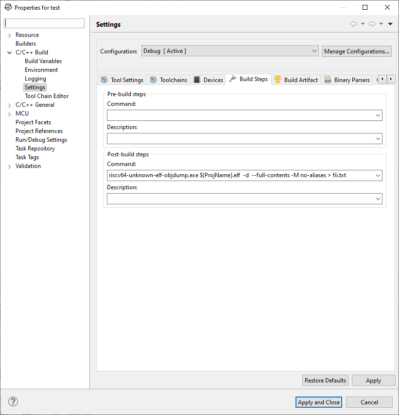
Figure 31 Post-build steps setting
| Option | Description |
| -d | Display assembler contents of executable sections |
| –full-contents | Display the full contents of all sections requested |
| -M | Pass text option on to the disassembler |
| No-aliases | Disassemble only into canonical instructions, rather than into pseudo-instructions |
| numeric | Print numeric register names, rather than ABI names |
Table 2 Option description in riscv64-unknown-elf-objdump.exe
Exercise
- Create a new C project to print “This is my first program!” using UART interface
- Create a new C project to lit the LEDs from the right to the left (LED0 to LED7). When it reaches the left most LED (LED7), returns to the right (LED0). The lit time and the shift interval is approximately 1s.
References
- “RISC-V | Wikiwand”, Wikiwand, 2020. [Online]. Available: https://www.wikiwand.com/en/RISC-V. [Accessed: 27- Oct- 2020].
- “RISC-V Books – RISC-V International”, RISC-V International, 2020. [Online]. Available: https://riscv.org/community/learn/risc-v-books/. [Accessed: 27- Oct- 2020].
- “Freedom Studio Version 2019.03 – SiFive”, https://www.sifive.com/share.png, 2020. [Online]. Available: https://www.sifive.com/blog/freedom-studio-version-2019.03. [Accessed: 27- Oct- 2020].
- “Memory Region Attributes (Debugging with GDB)”, Sourceware.org, 2020. [Online]. Available: https://sourceware.org/gdb/current/onlinedocs/gdb/Memory-Region-Attributes.html. [Accessed: 27- Oct- 2020].
- “Linker Scripts for MSP430G2553 · MSP430-GCC”, Nhivp.github.io, 2020. [Online]. Available: https://nhivp.github.io/msp430-gcc/2018-07-19/linker-scripts. [Accessed: 27- Oct- 2020].