
C Programming (2) on RISCV FII-PRX100 (ARTIX-7, XC7A100T) XILINX FPGA Board with our FII-Risc-V CPU (RV32G2.0)
V1.0
Fraser Innovation inc
RISCV FII-PRX100 (ARTIX-7, XC7A100T) XILINX FPGA Board C Programming 2
Version Control
| Version | Date | Description |
| 1.0 | 10/17/2020 | Initial Release |
Copyright Notice:
© 2020 Fraser Innovation Inc ALL RIGHTS RESERVED
Without written permission of Fraser Innovation Inc, no unit or individual may extract or modify part of or all the contents of this manual. Offenders will be held liable for their legal responsibility.
Thank you for purchasing the FPGA development board. Please read the manual carefully before using the product and make sure that you know how to use the product correctly. Improper operation may damage the development board. This manual is constantly updated, and it is recommended that you download the latest version when using.
Official Shopping Website:
https://fpgamarketing.com/FII-PRX100-D-ARTIX-100T-XC7A100T-RISC-V-FPGA-Board-PRX100-D-1.htm
Contents
1. RISCV FII-PRX100 (ARTIX-7, XC7A100T) Xilinx FPGA Board 4
2. Schematics Analysis 6
3. Address Map 9
4. RISCV_seg_cnt Project 10
5. RISCV_button Project 23
6. RISCV_timer_irq Project 26
7. RISCV_seg_irq Project 39
8. Exercise 46
9. References 47
RISCV FII-PRX100 (ARTIX-7, XC7A100T) Xilinx FPGA Board
RISCV FII-PRX100 Xilinx FPGA board has two versions, one has SRAM, denotes as PRX100-S, the other has DDR instead of SRAM, denotes as PRX100-D (https://fpgamarketing.com/FII-PRX100-D-ARTIX-100T-XC7A100T-RISC-V-FPGA-Board-PRX100-D-1.htm). See Figure 1 and 2 for different versions of PRX100. The difference could be easily found by observing the highlighted area on board. DDR version has an obvious IC on the front marked as “DDR”.
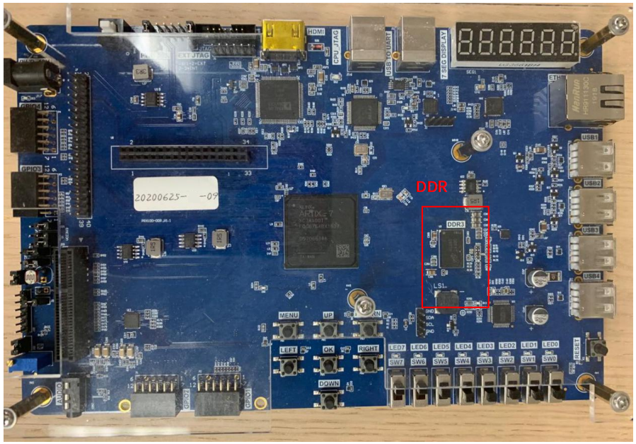
Figure 1 PRX100-D, DDR version
Take PRX100-S as an example, the two interfaces JTAG and UART have been highlighted in Figure 2. Note to connect jumper J6 1-2 to use J4 or J5 as external download interface as shown in Figure 3. JTAG interface is used to program
FPGA. UART interface is used to output to the computer. Before using Freedom Studio to run the C program, the FPGA board needs to be programmed with RISCV verilog project.
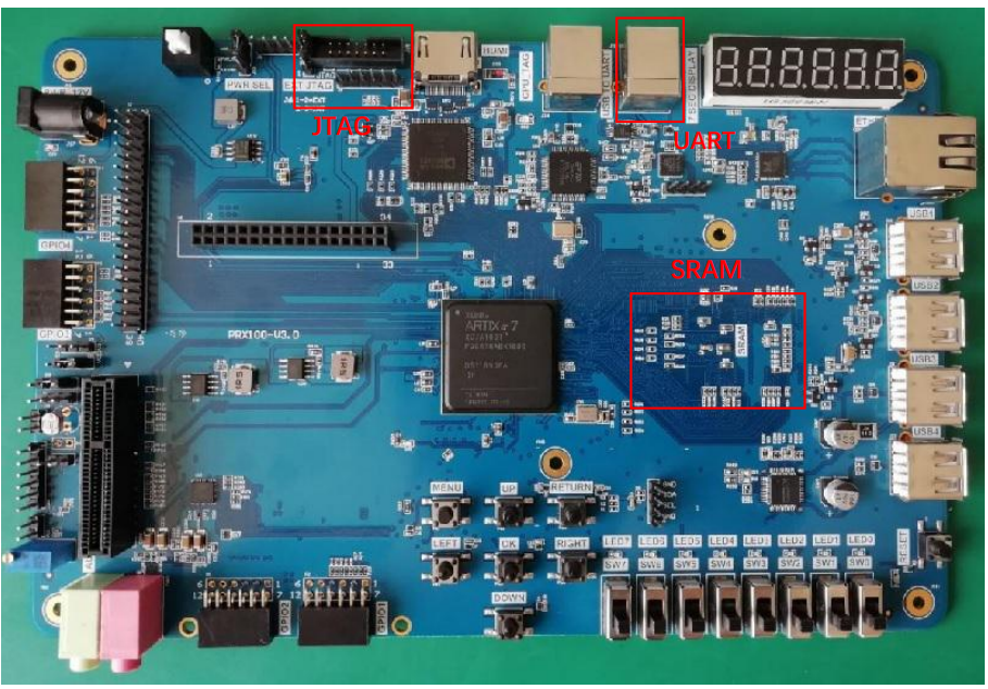
Figure 2 PRX100-S, SRAM version
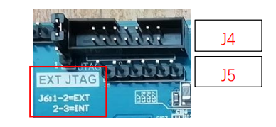
Figure 3 JTAG interface
Schematics Analysis
LEDs, buttons, and segment display will be used in the following projects, so an analysis of schematics is helpful to understand the variable assignments when writing the C programs.
- LED
It can be seen that to lit the LEDs, the current must flow from the left side to the right side. Since the left side is a constant high voltage, the right side is FPGA wiring. Only if the FPGA wiring is in low voltage, the left side voltage is higher than the right side voltage, thus the current would flow through LEDs, and the LEDs will be lit. On the opposite, when FPGA wiring is in high voltage, both the two sides of LEDs are in high voltages, thus no current flowing through, and LEDs will remain off.

Figure 4 LED wiring of schematics
- Button
In this case, buttons are considered as inputs. When pressing the push buttons, the PB will connect the left and right side wiring, otherwise, it can be considered as an open circuit. When the PB is pressed, and the connection is on, the VCC voltage will drop through a resistor, and then connects to ground. Thus FPGA wiring will connect to ground directly, thus in low voltage. If the PB is open circuit, there is no way VCC could flow, thus no current flow through the resistors, and the FPGA wiring will have the same voltage as VCC.
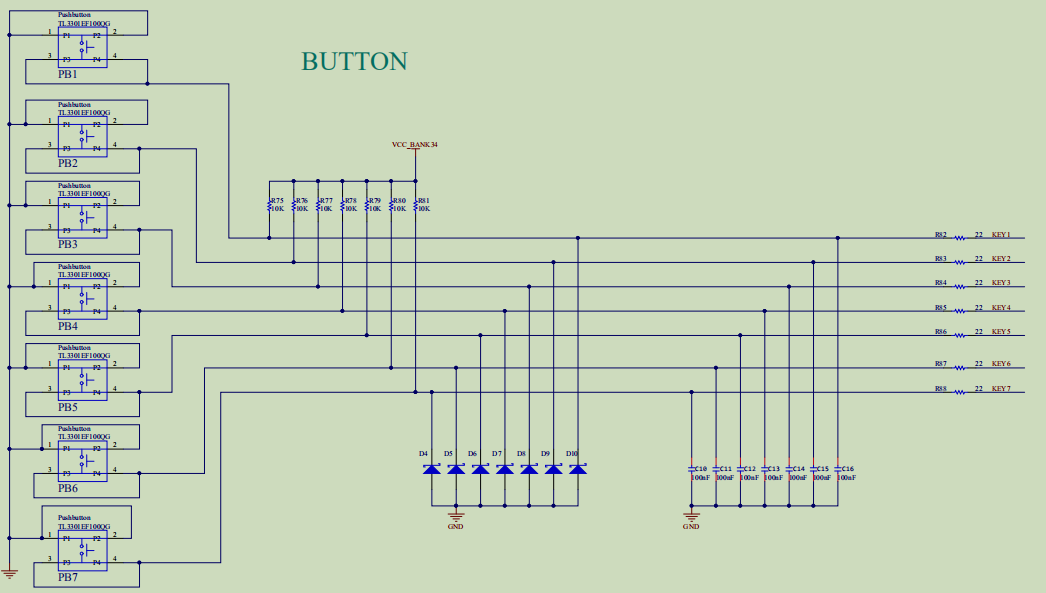
Figure 5 Button wiring of schematics
- Segment Display
Segment display have two types of FPGA wiring, location selection and segment selection. Since location selection is connected to P-channel field-effect transistor (FET), the gate must be more negative than the source for a typically 0.78V [1], so that VCC can flow through the segment display. Thus to lit the segment display, location selection must be in low voltage. Similarly, if the segment selection is also in low voltage (assume the corresponding location selection is in low voltage, so that the VCC could flow through the segment display), so there is a voltage difference between segment selection and VCC, VCC could flow from the right side of the segment display to the left side. On the opposite, if segment selection is in high voltage, there is no voltage difference between the left and right side of the segment display, and thus the segment display will be off.
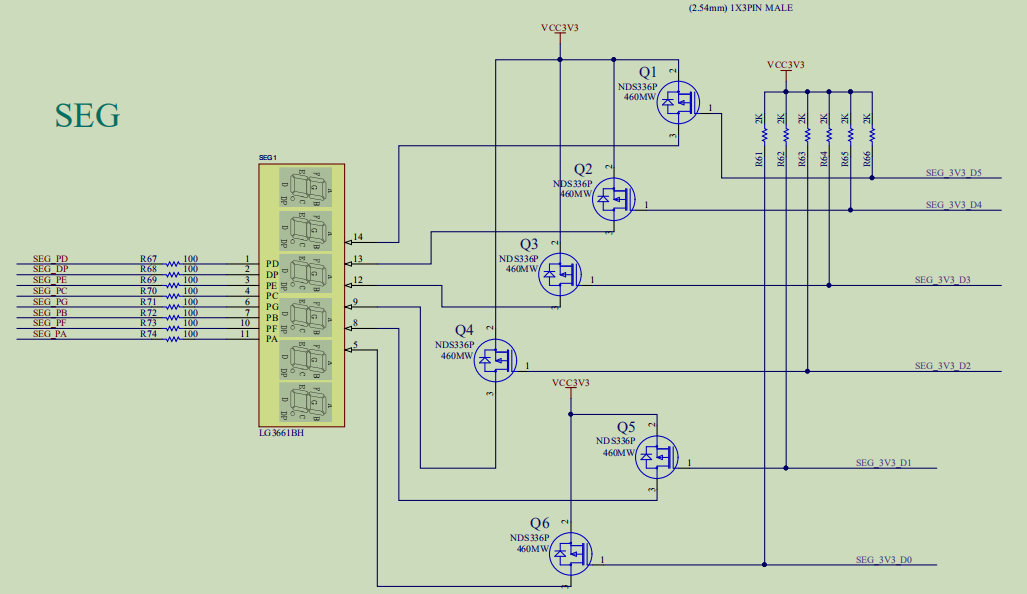
Figure 6 Segment display wiring of schematics
Address Map
Here is a screenshot of the address allocation, which is helpful when writing the C project, as shown in Figure 7.
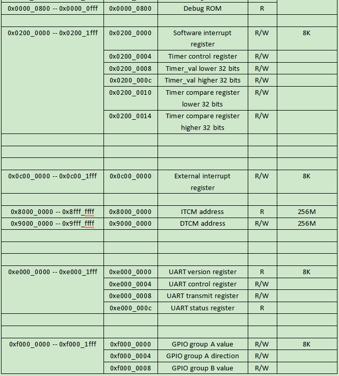
Figure 7 Address allocation
RISCV_seg_cnt Project
As shown in Figure 8, firstly, select the tab of the Freedom Studio under File > Import, the import window will pop up. Under the General tab, choose Existing Projects into Workspace, and click Next. In Figure 9, browse for the designed projects, click Copy projects into workspace box, and click Finish.
Then RISCV_seg_cnt project will appear under Project Explorer tab as shown in Figure 10.

Figure 8 Import window (1)
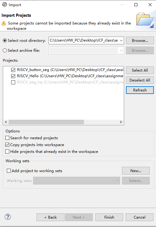
Figure 9 Import window (2)
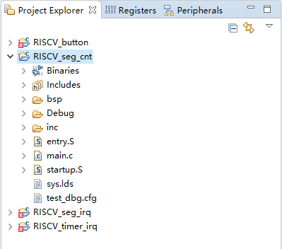
Figure 10 RISCV_seg_cnt in Project Explorer
After adding the project into the workspace, right click the project folder under Project Explorer, click Clean Project (do it every time before actually building the projects). Then click Build Project. After the console displays “ Build Finished”, click Refresh to refresh the project as shown in Figure 11 and Figure 12. Then to start debugging, right click the project, and select Debug As > Debug Configurations.
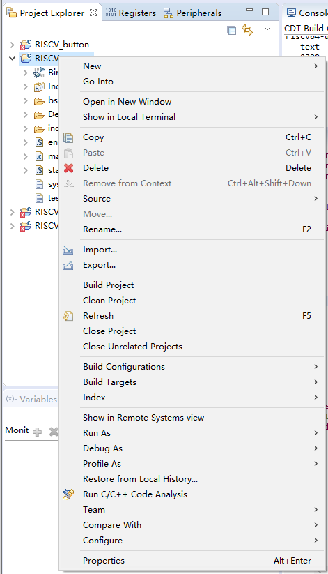
Figure 11 Clean, build and refresh the project
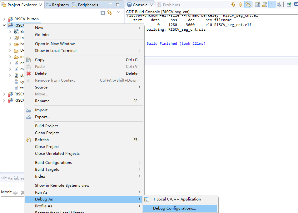
Figure 12 Debug
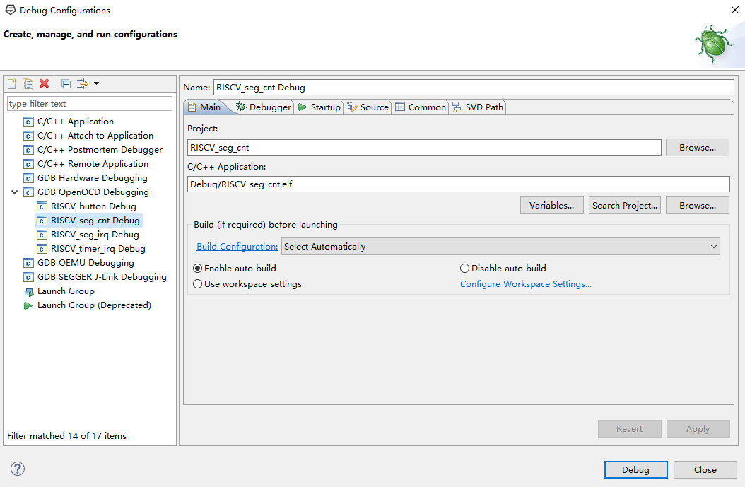
Figure 13 Debug Configurations
In the pop up windows as shown in Figure 13, set up the debug configuration as stated in C programming 1. Under GDB OpenOCD Debugging, add a new launch configuration by clicking the icon on the top left corner. Usually after building projects, with refresh, the C/C++ Application row will fill up the corresponding *.elf file automatically. If not, click Search Project under the blank, to search for the *.elf file. Or else, use Browse button to find the *.elf file under debug folder (this will be an absolute path). After all done of those, click Debug to load the program. Assuming the RISCV FII-PRX100-S XILINX FPGA Board is programmed with FII-RISCV3.01, the experiment phenomena can be observed that the segment display will continue counting.
Next, the detailed explanation of the software code to lit the segment display will be commented in each code block. They are as follows:
- Platform.h
#ifndef __PLATFORM_H
#define __PLATFORM_H
#ifdef __cplusplus
extern “C” {
#endif
#include “fii_types.h”//data type definition
#include “fii_gpio.h”//gpio definition
#include “fii_uart.h”//uart definition
#include “fii_irq.h”//interrupt definition
#include “encoding.h”//parameter definition
#define RAM_ADDR 0x90000000 //define DTCM address
//define a convenient way to access the address
#define GPIO_REG(offset) (*(volatile unsigned int *)(GPIO_ADDR + offset))
#define RAM_REG(offset) (*(volatile unsigned int *)(RAM_ADDR + offset))
#define UART_REG(offset) (*(volatile unsigned int *)(UART_BASE + offset))
#define TIME_REG(offset) (*(volatile unsigned int *)(TIME_ADDR + offset))
#ifdef __cplusplus
}
#endif
#endif // __PLATFORM_H
- Fii_types.h
/*
C type | Bytes in RV32 | Bytes in RV64
char | 1 | 1
short | 2 | 2
int | 4 | 4
long | 4 | 8
long long | 8 | 8
void* | 4 | 8
float | 4 | 4
double | 8 | 8
long double | 16 | 16
*/
//declare FII data types, aim to eliminate the conflict when cooperating with others
#ifndef __FII_TYPES_H
#define __FII_TYPES_H
#ifdef __cplusplus
extern “C” {
#endif
#define RV_TYPE RV32 //define FII-RISCV CPU to be 32 bits
typedef unsigned int uintptr_t;
typedef unsigned long long u64_t;
typedef unsigned int u32_t;
typedef unsigned short u16_t;
typedef unsigned char u8_t;
typedef long long s64_t;
typedef int s32_t;
typedef short s16_t;
typedef char s8_t;
#if 0
#if (RV_TYPE == RV32)
typedef unsigned long u32_t;
typedef long s32_t;
#elif (RV_TYPE == RV64)
typedef unsigned long u64_t;
typedef long s64_t;
#endif
#endif
#ifdef __cplusplus
}
#endif
#endif // __FII_TYPES_H
- Fii_gpio.h
#ifndef __FII_GPIO_H
#define __FII_GPIO_H
#ifdef __cplusplus
extern “C” {
#endif
//declare the segment display fonts
//the actual value is related to FII-RISCV gpio definition
//EXAMPLE: 8-seg display
//SEG_C:0X39
//DP G F E D C B A
//0 0 1 1 1 0 0 1
#define SEG_S 0x6D
#define SEG_A 0x77
#define SEG_B 0x7C
#define SEG_C 0x39
#define SEG_D 0x5E
#define SEG_E 0x79
#define SEG_F 0x71
#define SEG_0 0x3F
#define SEG_1 0x06
#define SEG_2 0x5B
#define SEG_3 0x4F
#define SEG_4 0x66
#define SEG_5 0x6D
#define SEG_6 0x7D
#define SEG_7 0x07
#define SEG_8 0x7F
#define SEG_9 0x67
#define SEG_j 0x40
#define SEG_p 0x80
#define SEG__ 0x00
#define BYTE_DELAY 0x00200000// macro definition
#define GPIO_ADDR 0xf0000000//define GPIO base address
//define offset address related to the GPIO base address
#define LED_VAL 0x00//LED value
#define LED_DIR 0x04//LED direction (I/O)
#define SEAT_VAL 0x08//segment location (one of six segment display)
#define SEAT_DIR 0x0C//segment location direction (I/O)
#define SEG_VAL 0x10//segment selection (A,B,C,D,E,F,G,DP)
#define SEG_DIR 0x14//segment selection direction (I/O)
#define BUT_VAL 0x18//button value
#define BUT_DIR 0x1C//button direction (I/O)
//===============================================
//===============================================
#define SEG_POS 0x07
#ifdef __cplusplus
}
#endif
#endif /* end __FII_GPIO_H */
- Fii_uart.h
- Main.c
#ifndef __FII_UART_H
#define __FII_UART_H
#ifdef __cplusplus
extern “C” {
#endif
//===============================================
#define UART_BASE 0xe0000000//define UART base address
//define offset address related to the UART base address
#define UART_VER 0x00//define UART version
#define UART_RUN 0x04//define UART enable
#define UART_DATA 0x08//define UART data
#define UART_RDY 0x0C//define UART ready (read only)
//===============================================
int send_to_uart(const void* ptr, int len);//declaration of UART send function
//===============================================
#ifdef __cplusplus
}
#endif
#endif /* __FII_UART_H */
#include <stdio.h> //include the standard I/O library, mainly used to declare printf function
#include “platform.h”//user defined function in C library, including GPIO configuration, definition of the memory,
//and related subfunctions and parameters
#define NOP_DELAY 0x100//define a macro
const unsigned char font[] = //declaration of an array of indexing the segment display font, here hexadecimal (0~f) is used
{
SEG_0, SEG_1, SEG_2, SEG_3,
SEG_4, SEG_5, SEG_6, SEG_7,
SEG_8, SEG_9, SEG_A, SEG_B,
SEG_C, SEG_D, SEG_E, SEG_F
};
//function used to delay
void delay_cnt (int cnt)
{
u32_t i;
for(i = 0; i < cnt ; i ++ )
asm(“nop”);
return;
};
int main(void)//define main function
{
//initialization segment display
unsigned int curr_seat = 0x01;//segment display initial location (the right most segment display)
unsigned int char_num = 0;//segment display initial value
unsigned int curr_num = 0;//lit time for segment display
unsigned int char_pos = 0;//array index for segment display font
//UART output
printf(“\r\nRiscV Program : Display segment number and print it. \r\n”);
//initialization GPIO
(*(volatile unsigned int *)(GPIO_ADDR + LED_VAL)) = ~0L;//led_value is 0, negation is applied for the LED wiring on schematics
(*(volatile unsigned int *)(GPIO_ADDR + LED_DIR)) = 0;//LED’s direction is output
(*(volatile unsigned int *)(GPIO_ADDR + SEAT_DIR)) = 0;//segment location value’s direction is output
(*(volatile unsigned int *)(GPIO_ADDR + SEG_DIR)) = 0;//segment selection value’s direction is output
while ( 1 )//main loop
{
(*(volatile unsigned int *)(GPIO_ADDR + SEG_VAL)) = ~font[char_pos & 0xf];//set the segment display index
//negation is applied for the wiring on schematics
(*(volatile unsigned int *)(GPIO_ADDR + SEAT_VAL)) = ~curr_seat;//set the segment display location
//negation is applied for the wiring on schematics
delay_cnt (NOP_DELAY);//set time delay
curr_seat = curr_seat << 1;//shift the lit segment display to the left 1 bit
if(curr_seat == 0x40) //decision making, if the segment display location is the left most
{
curr_seat = 0x01;//reset it to the right most
curr_num ++ ;//counter +1
if(curr_num % 1000 == 9)//prevent multiple print, print once every 1000 iterations
{
char_num ++ ;//segment display value +1
printf(“seg cnt num = 0x%06x \r\n”, char_num);
}
char_pos = char_num;//pass the segment display value to the index font
}
else char_pos = char_pos >> 4;//right shift the current segment display value by 4 (hexadecimal by 1 bit)
}
}
RISCV_button Project
Same as the previous steps, import the project into the Freedom Studio, as shown in Figure 14. The experiment phenomenon is that when pressing the buttons (only three buttons are implemented here: menu, up, and return), the corresponding segment display will change from ‘1’ to ‘0’.
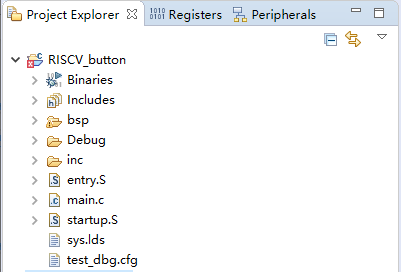
Figure 14 RISCV_button project
Except for the main function of RISCV_button is different than that of RISCV_seg_cnt, the other header files are all the same. Therefore, only main.c file will be listed here. The detailed explanation will be commented in the code block.
- Main.c
#include <stdio.h>//include the standard I/O library, mainly used to declare printf function
#include “platform.h”//user defined function in C library, including GPIO configuration, definition of the memory,
//and related subfunctions and parameters
#define NOP_DELAY 0x00000200//define a macro, the value is different than that in RISCV_seg_cnt. It can be modified according to
//the needs
int main(void)//main function for RISCV_button function
{
unsigned int curr_seat = 0x01;//segment display initial location (the right most segment display)
volatile unsigned int i;//used in the delay loop
unsigned int curr_gpio_val;//read the button input
(*(volatile unsigned int *)(GPIO_ADDR + SEAT_DIR)) = 0;//segment location value’s direction is output
(*(volatile unsigned int *)(GPIO_ADDR + SEG_DIR)) = 0;//segment selection value’s direction is output
(*(volatile unsigned int *)(GPIO_ADDR + BUT_DIR)) = ~0L;//button direction is input (note there is a negation)
(*(volatile unsigned int *)(GPIO_ADDR + SEG_VAL)) = ~SEG__;//initialize the current segment display to be empty (no display)
//negation is applied for the segment display wiring on schematics
printf(“\r\nThis is a button test program. \r\n”);
while (1)//main loop
{
curr_gpio_val = (*(volatile unsigned int *)(GPIO_ADDR + BUT_VAL));//read the button input
(*(volatile unsigned int *)(GPIO_ADDR + SEAT_VAL)) = ~curr_seat;//set the segment display location
//negation is applied for the wiring on schematics
if(curr_gpio_val & curr_seat)//decision making, if it is not the corresponding location
//button and the corresponding segment display location are bitwise equal
//button is negation for the wiring on schematics
(*(volatile unsigned int *)(GPIO_ADDR + SEG_VAL)) = ~SEG_1;//display 1
else//if it is the corresponding location
(*(volatile unsigned int *)(GPIO_ADDR + SEG_VAL)) = ~SEG_0;//display 0
for(i = 0; i < NOP_DELAY; i ++ )//time delay for the segment display
asm(“nop”);
curr_seat = curr_seat << 1;//shift the lit segment display to the left 1 bit
if(curr_seat == 0x08) curr_seat = 0x01;//decision making, if the segment display location is exceeds the 3rd
//3 segment display corresponding 3 push buttons
}
}
RISCV_timer_irq Project
Before diving into the project, a simple introduction of interrupt should be mentioned. In digital computers, interrupts are the processor’s response to events that require software attention. The interrupt condition will warn the processor and use it as a request to the processor to interrupt the currently executing code when allowed so that the event can be processed in time. If the request is accepted, the processor will respond by suspending its current activity, saving its state, and executing a function called an interrupt handler (or interrupt service routine, ISR) to handle the event. The interrupt is temporary, and unless the interrupt indicates a fatal error, the processor will resume normal activity after the interrupt handler completes [2].
More complicatedly, processors may face the situation to handle multiple interrupts. In that case, interrupt priority level (IPL) should be considered. Usually, only one interrupt is allowed at one time, other interrupts shall wait until it completes. Sometimes, interrupts may occur during the interrupt handling, it is called nested interrupt.
RISCV_timer_irq avoids complicated interrupt occurrence. Machine timer interrupt is implemented here.
Import the project as the same steps with the previous projects. The corresponding Freedom Studio project explorer is shown in Figure 15.
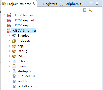
Figure 15 RISCV_timer_irq
A new header file fii_irq.h is used here. Except for that, entry.S and main.c will be introduced as well. The rest of the header files are the same as the previous projects.
- Fii_irq.h
#ifndef __FII_IRQ_H
#define __FII_IRQ_H
#ifdef __cplusplus
extern “C” {
#endif
#include “fii_types.h”
#include “encoding.h”
#define CLINT_CTRL_ADDR (0x02000000)//define kernel interrupt base address
#define PLIC_CTRL_ADDR (0x0C000000)//define external interrupt base address
#define TIME_ADDR CLINT_CTRL_ADDR //timer interrupt address
#define RTC_FREQ 32768//RTC timer frequency
#define MCAUSE_INT 0x80000000//mcause bit 31 mask, decision making, ‘1’ is interrupt, ‘0’ is exception
#define MCAUSE_CAUSE 0x7FFFFFFF//mcause bit 30-0 mask, decision making, exception code
//here, machine timer interrupt exception code is ‘7’
//offset with respect to the kernel interrupt base address
#define CLINT_CTRL_REG (0x0000 << 2)//0x0000, timer register
#define TM_CTRL_REG (0x0001 << 2)//0x0004, timer control register
#define TM_L_REG (0x0002 << 2)//0x0008, timer_val register lower 32 bits
#define TM_H_REG (0x0003 << 2)//0x000c, timer_val register higher 32 bits
#define TMCMP_L_REG (0x0004 << 2)//0x0010, timer cmp register lower 32 bits
#define TMCMP_H_REG (0x0005 << 2)//0x0014, timer cmp register higher 32 bits
unsigned int handle_trap(unsigned int mcause, unsigned int epc);//define interrupt entrance function
#ifdef __cplusplus
}
#endif
#endif // __FII_IRQ_H
It should be mentioned that the implementation of mcause register is following the definition in version 1.9 “RISC-V instruction set manual privileged architecture”. As shown in Figure 16.
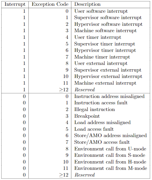
Figure 16 mcause register (bit 31= interrupt, bit 30-0 =exception code)
The interrupt project will use entry.S file, which is used for invoking the interrupt entrance function. In the initialization function of the main program, the address of trap_entry will be assigned to the RISCV CPU control and status register (CSR) mtvec. When the interrupt actually happens, the RISCV CPU program counter (PC) will suspend from the main execution, and points to the address of trap_entry function instead. After the interrupt handler completes, PC resumes the main execution.
- Entry.S
.equ REGBYTES, (1 << 2)#define REGBYTES to be 4
#.file “encoding.h”
.section .text.entry #define it to be the code
.align 2#2^2 = 4 bytes aligned
.global trap_entry#declaration of global function
trap_entry:#function actual starting point
ADDI sp, sp, -32*REGBYTES # REGBYTES = 4 #free stack depth to store
#store x1-x31 register value to the stack
SW x1, 1*REGBYTES(sp)
SW x2, 2*REGBYTES(sp)
SW x3, 3*REGBYTES(sp)
SW x4, 4*REGBYTES(sp)
SW x5, 5*REGBYTES(sp)
SW x6, 6*REGBYTES(sp)
SW x7, 7*REGBYTES(sp)
SW x8, 8*REGBYTES(sp)
SW x9, 9*REGBYTES(sp)
SW x10, 10*REGBYTES(sp)
SW x11, 11*REGBYTES(sp)
SW x12, 12*REGBYTES(sp)
SW x13, 13*REGBYTES(sp)
SW x14, 14*REGBYTES(sp)
SW x15, 15*REGBYTES(sp)
SW x16, 16*REGBYTES(sp)
SW x17, 17*REGBYTES(sp)
SW x18, 18*REGBYTES(sp)
SW x19, 19*REGBYTES(sp)
SW x20, 20*REGBYTES(sp)
SW x21, 21*REGBYTES(sp)
SW x22, 22*REGBYTES(sp)
SW x23, 23*REGBYTES(sp)
SW x24, 24*REGBYTES(sp)
SW x25, 25*REGBYTES(sp)
SW x26, 26*REGBYTES(sp)
SW x27, 27*REGBYTES(sp)
SW x28, 28*REGBYTES(sp)
SW x29, 29*REGBYTES(sp)
SW x30, 30*REGBYTES(sp)
SW x31, 31*REGBYTES(sp)
#pass the arguments before (input a0, a1, a2) and after (return a0) calling function handle_trap
csrr a0, mcause#x[a0] = CSRs[mcause]
csrr a1, mepc#x[a1] = CSRs[mepc]
mv a2, sp#x[a2] = x[sp]
call handle_trap#invoke handle_trap function
csrw mepc, a0#CSRs[mepc] = x[a0]
#load x1-x31 register value from stack
LW x1, 1*REGBYTES(sp)
LW x2, 2*REGBYTES(sp)
LW x3, 3*REGBYTES(sp)
LW x4, 4*REGBYTES(sp)
LW x5, 5*REGBYTES(sp)
LW x6, 6*REGBYTES(sp)
LW x7, 7*REGBYTES(sp)
LW x8, 8*REGBYTES(sp)
LW x9, 9*REGBYTES(sp)
LW x10, 10*REGBYTES(sp)
LW x11, 11*REGBYTES(sp)
LW x12, 12*REGBYTES(sp)
LW x13, 13*REGBYTES(sp)
LW x14, 14*REGBYTES(sp)
LW x15, 15*REGBYTES(sp)
LW x16, 16*REGBYTES(sp)
LW x17, 17*REGBYTES(sp)
LW x18, 18*REGBYTES(sp)
LW x19, 19*REGBYTES(sp)
LW x20, 20*REGBYTES(sp)
LW x21, 21*REGBYTES(sp)
LW x22, 22*REGBYTES(sp)
LW x23, 23*REGBYTES(sp)
LW x24, 24*REGBYTES(sp)
LW x25, 25*REGBYTES(sp)
LW x26, 26*REGBYTES(sp)
LW x27, 27*REGBYTES(sp)
LW x28, 28*REGBYTES(sp)
LW x29, 29*REGBYTES(sp)
LW x30, 30*REGBYTES(sp)
LW x31, 31*REGBYTES(sp)
addi sp, sp, 32*REGBYTES#return the stack pointer to the original location
mret#resume the pc
.weak handle_trap
handle_trap:
1:
j 1b
As shown in Figure 17, the principle of stack used above is as follows:
1: the location of the stack pointer before the interrupt
2: just before entering the interrupt, the stack pointer is moved to -32 x 4 bytes location
3: store 31 registers value between 1-2, and the stack pointer stays at location 2
4: before the interrupt finishes, load the data between 3 and 4 back to the 31 registers, and move the stack pointer back to 4.
Note that after the whole procedure, the stack pointer returns to its origin location. Although the stack leaves space for all 32 registers, x0 is hardwired to 0, the value is not changing, so only 31 registers will be operated.
pop
32 x 4 bytes
push
Figure 17 Stack principle
- Main.c
#include <stdio.h> //include the standard I/O library, mainly used to declare printf function
#include “platform.h”//user defined function in C library, including GPIO configuration, definition of the memory,
//and related subfunctions and parameters
extern void trap_entry();//declaration that trap_entry function is invoked from outside (entry.S)
void set_timer(u64_t msec)//define a function to set timer
{
//define 64 bits timers using 2*32 bits registers
u64_t now;//define 64 bits timer value ‘now’
now = TIME_REG(TM_H_REG);//fill the high 32-bits
now = now << 32;//move the high 32-bits into the right place
now |= TIME_REG(TM_L_REG);//bitwise or with the lower 32 bits
//add time on the current timer, in milisec (msec), to get the 64 bits new timer ‘then’
u64_t then = now + msec*(RTC_FREQ/1000);//conversion from RTC_FREQ (32768) to msec (1000)
//write ‘then’ timer low 32 bits into timer compare register low 32 bits
TIME_REG( TMCMP_L_REG ) = then & 0xffffffff;
TIME_REG( TMCMP_H_REG ) = then >> 32;//write ‘then’ timer high 32 bits into timer compare register high 32 bits
return;
}
//timer counter
unsigned int time_cnt = 0;
/*Entry Point for Machine Timer Interrupt Handler*/
void handle_m_time_interrupt(){
clear_csr(mie, MIP_MTIP);//mie bit 7 is machine mode timer interrupt enable
// clear MIP_MTIP bit right after entering the interrupt handler
//prevent the nested interrupt
set_timer(250); // reset the timer for 250ms
// read the current value of the LEDs and invert them.
if((time_cnt % 4 ) == 0) // 1s, 250ms*4
{
GPIO_REG(LED_VAL) = ~((time_cnt >> 2) & 0xff);//display LEDs every 1s, only reserve the significant 8 bits
//only 8 bits LED (0xff), negation is from the LED wiring of schematics
printf(“time_irq = 0x%08x \r\n”, time_cnt); //print timer counter every 4 times entering the interrupt
}
time_cnt ++;//timer counter increment
// Re-enable the timer interrupt.
set_csr(mie, MIP_MTIP);//mie bit 7 is machine mode timer interrupt enable
// set MIP_MTIP bit before finishing the interrupt
}
//define a general interrupt entrance function
unsigned int handle_trap(unsigned int mcause, unsigned int epc)
{
//decision making
//whether it’s a interrupt or exception (mcause bit 31)
//whether the exception code is 7 (mcause bit 30-0)
//both satisfied, timer interrupt confirmed
if ((mcause & MCAUSE_INT) && ((mcause & MCAUSE_CAUSE) == IRQ_M_TIMER))
{
handle_m_time_interrupt();//invoke the interrupt handler
}
else
{
//print debug information
printf(“There is not any handle_trap available \n”);
printf(“mstatus = 0x%08x\n” , read_csr(mstatus) );//mstatus: machine status register
printf(“mie = 0x%08x\n” , read_csr(mie) );//mie: machine interrupt-enable register
printf(“mcause = 0x%08x\n” , read_csr(mcause) );//mcause: machine trap cause
printf(“mtvec = 0x%08x\n” , read_csr(mtvec)); //mtvec: machine trap-handler base address
}
return epc;
}
//initialization function
void _init(void)
{
time_cnt = 0;//initialize the timer counter
printf(“Program Initial… \n”);
write_csr(mtvec, &trap_entry);//assign the address of trap_entry to mtvec
//when interrupt begins, PC moves to trap_entry
return;
}
//initialization of LED
static void init_led(void)
{
GPIO_REG(LED_VAL) = ~0L; //init LED output value is ‘0’
//negation is from the LED wiring of schematics
GPIO_REG(LED_DIR) = 0; //init LED gpio direction is output
return;
}
int main(void)//main function
{
int i = 0;//used for delay loop
_init();//initialization
printf(“\r\nRiscV Program : Invoke timer IRQ. \r\n”);
init_led();//LED initialization
set_timer(250);//first time set timer
set_csr(mie, MIP_MTIP);//enable timer interrupt
write_csr(mstatus, MSTATUS_MIE); // enable all machine mode interrupt
TIME_REG( TM_CTRL_REG ) = 0x80000001;//timer enable, and start to count using timer
while ( 1 )//loop
{
for(i = 0; i < 0x100000; i ++ )
asm(“nop”);//assembly operation ‘nop’ every 0x100000
}
}
RISCV_seg_irq Project
Next, timer interrupt project and segment display project are combined together, to be the RISCV_seg_irq project. Import the project following the same procedure as before. Only main.c file is slightly different than that in RISCV_timer_irq.
- Main.c
#include <stdio.h> //include the standard I/O library, mainly used to declare printf function
#include “platform.h”//user defined function in C library, including GPIO configuration, definition of the memory,
//and related subfunctions and parameters
#define NOP_DELAY 0x100//define a macro
extern void trap_entry();//declaration that trap_entry function is invoked from outside (entry.S)
void set_timer(u64_t msec)//define a function to set timer
{
//define 64 bits timers using 2*32 bits registers
u64_t now;//define 64 bits timer value ‘now’
now = TIME_REG(TM_H_REG);//fill the high 32-bits
now = now << 32;//move the high 32-bits into the right place
now |= TIME_REG(TM_L_REG);//bitwise or with the lower 32 bits
//add time on the current timer, in milisec (msec), to get the 64 bits new timer ‘then’
u64_t then = now + msec*(RTC_FREQ/1000);//conversion from RTC_FREQ (32768) to msec (1000)
//write ‘then’ timer low 32 bits into timer compare register low 32 bits
TIME_REG( TMCMP_L_REG ) = then & 0xffffffff;
TIME_REG( TMCMP_H_REG ) = then >> 32;//write ‘then’ timer high 32 bits into timer compare register high 32 bits
return;
}
//timer counter
unsigned int time_cnt = 0;
/*Entry Point for Machine Timer Interrupt Handler*/
void handle_m_time_interrupt(){
clear_csr(mie, MIP_MTIP);//mie bit 7 is machine mode timer interrupt enable
// clear MIP_MTIP bit right after entering the interrupt handler
//prevent the nested interrupt
// Reset the timer for 3s in the future.
// This also clears the existing timer interrupt.
set_timer(500); // reset the timer for 500ms
// read the current value of the LEDs and invert them.
if((time_cnt % 4 ) == 0) // 2s, 500ms*4
{
GPIO_REG(LED_VAL) = ~((time_cnt >> 2) & 0xff);//display LEDs every 2s, only reserve the significant 8 bits
//only 8 bits LED (0xff), negation is from the LED wiring of schematics
printf(“time_irq = 0x%08x \r\n”, time_cnt); //print timer counter every 4 times entering the interrupt
}
time_cnt ++;//timer counter increment
// Re-enable the timer interrupt.
set_csr(mie, MIP_MTIP);//mie bit 7 is machine mode timer interrupt enable
// set MIP_MTIP bit before finishing the interrupt
}
//define a general interrupt entrance function
unsigned int handle_trap(unsigned int mcause, unsigned int epc)
{
//decision making
//whether it’s a interrupt or exception (mcause bit 31)
//whether the exception code is 7 (mcause bit 30-0)
//both satisfied, timer interrupt confirmed
if ((mcause & MCAUSE_INT) && ((mcause & MCAUSE_CAUSE) == IRQ_M_TIMER))
{
handle_m_time_interrupt();//invoke the interrupt handler
}
else
{
//print debug information
printf(“There is not any handle_trap available \n”);
printf(“mstatus = 0x%08x\n” , read_csr(mstatus) );//mstatus: machine status register
printf(“mie = 0x%08x\n” , read_csr(mie) );//mie: machine interrupt-enable register
printf(“mcause = 0x%08x\n” , read_csr(mcause) );//mcause: machine trap cause
printf(“mtvec = 0x%08x\n” , read_csr(mtvec)); //mtvec: machine trap-handler base address
}
return epc;
}
//initialization function
void _init(void)
{
time_cnt = 0;//initialize the timer counter
printf(“RiscV Program : Display segment number and invoke timer IRQ \r\n”);
write_csr(mtvec, &trap_entry);//assign the address of trap_entry to mtvec
//when interrupt begins, PC moves to trap_entry
//added GPIO address initialization
(*(volatile unsigned int *)(GPIO_ADDR + SEAT_DIR)) = 0;//location selection
(*(volatile unsigned int *)(GPIO_ADDR + SEG_DIR)) = 0;//segment selection
return;
}
//declaration of an array of indexing the segment display font
//here hexadecimal (0~f) is used
const unsigned char font[] =
{
SEG_0, SEG_1, SEG_2, SEG_3,
SEG_4, SEG_5, SEG_6, SEG_7,
SEG_8, SEG_9, SEG_A, SEG_B,
SEG_C, SEG_D, SEG_E, SEG_F
};
//initialization of LED
static void init_led(void)
{
GPIO_REG(LED_VAL) = ~0L; //init LED output value is ‘0’
//negation is from the LED wiring of schematics
GPIO_REG(LED_DIR) = 0; //init LED gpio direction is output
return;
}
//added segment display function
//takes arguments of segment display font and location selection
void display_seg(unsigned char font_idx, unsigned int font_seat)
{
(*(volatile unsigned int *)(GPIO_ADDR + SEG_VAL)) = ~(font[font_idx]);//display font, negation is from the segment wiring of schematics
(*(volatile unsigned int *)(GPIO_ADDR + SEAT_VAL)) = ~font_seat;//location selection, negation is from the segment wiring of schematics
return;
}
int main(void)//main function
{
int i = 0;//used for delay loop
unsigned int curr_seat = 0x01;
unsigned int curr_seg = 0;
unsigned char out_char = 0;
_init();//initialization
printf(“\r\nRun Segment Timer IRQ Program \r\n”);
init_led();//LED initialization
set_timer(500);//first time set timer
set_csr(mie, MIP_MTIP);//enable timer interrupt
write_csr(mstatus, MSTATUS_MIE);// enable all machine mode interrupt
TIME_REG( TM_CTRL_REG ) = 0x80000001;//timer enable, and start to count using timer
while ( 1 )//main loop
{
display_seg(out_char, curr_seat);//invoke segment display function
for(i = 0; i < NOP_DELAY ; i ++ )
asm(“nop”);//assembly operation ‘nop’
curr_seat = curr_seat << 1;//shift the lit segment display to the left 1 bit
if(curr_seat == 0x40)//decision making, if the segment display location is the left most
{
curr_seg = time_cnt;//assign the timer counter to the segment display
curr_seat = 0x01;//reset it to the right most
}
else
curr_seg = curr_seg >> 4;//right shift the current segment display value by 4 (hexadecimal by 1 bit)
out_char = curr_seg & 0xf;//only display one hexadecimal number at one time
}
}
Exercise
- Create a new C project which inputs menu, up, and return 3 buttons, and the corresponding segment display will show 1, 2 and 3 respectively.
- Create a new C project to lit the LEDs from the right to the left (LED0 to LED7). When it reaches the left most LED (LED7), returns to the right (LED0). The lit time and the shift interval is approximately 1s. Use timer interrupt to accomplish it.
- Modify the RISCV verilog project and program the FPGA board, to implement the 8 slide switches in the GPIO group. Create a new project to lit the LEDs when sliding up the corresponding switches.
References
[1]2020. [Online]. Available: https://www.mouser.ca/ProductDetail/ON-Semiconductor-Fairchild/NDS336P?qs=QwEULm8S1DpwQ6VqpkXnVA==. [Accessed: 21- Oct- 2020].
[2]”Interrupt | Wikiwand”, Wikiwand, 2020. [Online]. Available: https://www.wikiwand.com/en/Interrupt. [Accessed: 20- Oct- 2020].

