Successfully compiled the simulation library
Experimental Manuals FII-PE7030 FPGA Board Based FPGA Products FPGA Tutor

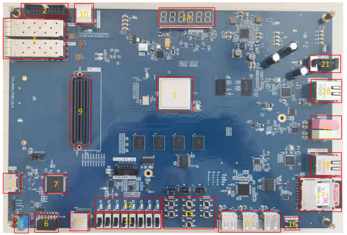
zynq xc7z030 board – FII-PE7030 Experiment 6 – Use of Multipliers and ISIM

Experiment 6 Use of Multipliers and ISIM 6.1 Experiment Objective Learn to use multiplier Use ISIM to simulate design output 6.2 Experiment Implement 8×8 multiplier, the first input value is an 8-bit switch, and the second input value is the output of an 8-bit counter. Observe the output in ISIM 6.3 Experiment 6.3.1 Program Design The first step: the establishment of the main program framework module mult_sim( input inclk_p, input inclk_n, input [7:0] sw, output [15:0] mult_res, output reg [7:0] count ); endmodule The second step: call multiplier IP core…

Read More
FII-PE7030-Physical-Picture
Experimental Manuals FII-PE7030 FPGA Board Based FPGA Products FPGA Tutor

EVB Board – Basic FPGA design training – FII-PE7030 User Experimental Manuals

Version Control Version Date Description V1.0 21/11/2019 Initial Release Contents Part One: Introduction to Zynq_7030 Development System 5 1、System Design Objective 5 2、System Resource 5 3、Human-computer Interaction Interface 5 4、Software Development System 6 5、Supporting Resources 6 6、Physical Display 6 Part Two: zynq_7030 Main Resources Usage and FPGA Development Experiemnt 8 Experiment 1 LED Shifting Design 9 1.1 Experiment Objective 9 1.2 Experiment Implement 9 1.3 Experiment 9 1.3.1 LED Introduction 9 1.3.2 Hardware Design 9 1.3.3 Program Design 10 1.4 Experiment Verification 26 Experiment 2 Analysis of Switch Signals via…

Read More
Experimental Manuals FII-PRX100-S FII-PRX100D FPGA Products FPGA Tutor PRX100 Risc-V

RISC-V FPGA Board Study Guide – FII-PRX100 Experimental Manuals

Version Control Version Date Descrption V1.0 10/07/2019 Initial Release V1.1 16/09/2019 Modify part of pin assignments and Ethernet description Contents: Part 1 FII-PRX100 Development System Introduction 5 1. System Design Objective 5 2. System Resource 5 3. Human-computer Interaction Interface 5 4. Software Development System 6 5. Supporting Resources 6 Part 2 FII-PRX100 Main Hardware Resources Usage and FPGA Development Experiment 6 Experiment 1 LED Shifting 6 1. Experiment Object 6 2. Create A New Project Under Vivado 6 Experiment 2 Switches and display 25 1.Experiment Objective 25 2.Start New…

Read More
Experimental Manuals FPGA Tutor Risc-V

AD,DA Experiment , write the data into PCF8591, Read the value of AD acquisition from PCF8591, – FII-PRA040 FPGA Board Experimental 12 – Altera Risc-V FPGA Tutorial :

Experiment 12 AD,DA Experiment 12.1 Experiment Objective Since in the real world, all naturally occurring signals are analog signals, and all that are read and processed in actual engineering are digital signals. There is a process of mutual conversion between natural and industrial signals (digital-to-analog conversion: DAC, analog-to-digital conversion: ADC). The purpose of this experiment is as follows: Learn about the theory of AD conversion Review the knowledge of the IIC protocol learned in the previous experiment and write the data into PCF8591 on the development board. Read the value…

Read More
Experimental Manuals FPGA Tutor Risc-V

Learning the basic principles of asynchronous IIC bus, and the IIC communication protocol, reading and writing EEPROM – Altera Risc-V IIC Protocol Transmission FPGA Tutorial – FII-PRA040 FPGA Board Experimental 11

Experiment 11 IIC Protocol Transmission 11.1 Experiment Objective Learning the basic principles of asynchronous IIC bus, and the IIC communication protocol Master the method of reading and writing EEPROM Joint debugging using logic analyzer 11.2 Experiment Implement Correctly write a number to any address in the EEPROM (this experiment writes to the register of 8’h03 address) through the FPGA (here changes the written 8-bit data value by (SW7~SW0)). After writing in successfully, read the data as well. The read data is displayed directly on the segment display. Download the program…

Read More
Experimental Manuals FPGA Tutor Risc-V

Asynchronous serial port communication, handshake mechanism, data frame, Asynchronous Serial Port Design and Experiment – FII-PRA040 Risc-V FPGA Board Experimental 10

Experiment 10 Asynchronous Serial Port Design and Experiment 10.1 Experiment Objective Because asynchronous serial ports are very common in industrial control, communication, and software debugging, they are also vital in FPGA development. the basic principles of asynchronous serial port communication, handshake mechanism, data frame Master asynchronous sampling techniques Review the frame structure of the data packet Learning FIFO Joint debugging with common debugging software of PC (SSCOM, teraterm, etc.) 10.2 Experiment Implement Design and transmit full-duplex asynchronous communication interface Tx, Rx Baud rate of 11520 bps, 8-bit data, 1 start…

Read More
Experimental Manuals FPGA Tutor Risc-V

Altera Risc-V FPGA Tutorial : Use Dual-port RAM to Read and Write Frame Data – FII-PRA040 FPGA Board Experimental 9

Experiment 9 Use Dual-port RAM to Read and Write Frame Data 9.1 Experiment Objective Learn to configure and use dual-port RAM Learn to use synchronous clock to control the synchronization of frame structure Learn to use asynchronous clock to control the synchronization of frame structure Experiment Implement Observing the synchronization structure of synchronous clock frames using SignalTap II Extended the use of dual-port RAM Design the use of three-stage state machine Design a 16-bit data frame Data is generated by an 8-bit counter: Data={~counta,counta} The ID of the data frame…

Read More
Experimental Manuals FPGA Tutor Risc-V

Altera Risc-V FPGA Tutorial : Use of ROM – Study the format of *.mif and how to edit *.mif file,Learn to use RAM, read and write RAM, FII-PRA040 FPGA Board Experimental 8

Experiment 8 Use of ROM 8.1 Experiment Objective Study the internal memory block of FPGA Study the format of *.mif and how to edit *.mif file to configure the contents of ROM Learn to use RAM, read and write RAM 8.2 Experiment Implement Design 16 outputs ROM, address ranging 0-255 Interface 8-bit switch input as ROM’s address Segment display the contents of ROM and require conversion of hexadecimal to BCD output. 8.3 Experiment 8.3.1 Introduction of the Program This experiment was carried out on the basis of Experiment 7, and…

Read More
Altera Risc-V FPGA Tutorial : Hexadecimal Number to BCD Code Conversion and Application Experimental
Experimental Manuals FPGA Tutor Risc-V

Altera Risc-V FPGA Tutorial : Hexadecimal Number to BCD Code Conversion and Application – FII-PRA040 FPGA Board Experimental 7

Experiment 7 Hexadecimal Number to BCD Code Conversion and Application Experiment Objective Learn to convert binary numbers to BCD code (bin_to_bcd) Learn to convert hexadecimal numbers to BCD code (hex_to_bcd) 7.2 Experimental Implement Combined with experiment 6, display the results of the operation to the segment display. 7.3 Experiment 7.2.1 Introduction to the principle of hexadecimal number to BCD code Since the hexadecimal display is not intuitive, decimal display is more widely used in real life. Human eyes recognition is relatively slow, so the display from hexadecimal to decimal does…

Read More
Experimental Manuals FPGA Tutor Risc-V

Use multiplier, Use ModelSim to simulate design output, Use of Multipliers and ModelSim – FII-PRA040 Altera Risc-V FPGA Board Experimental 6

Experiment 6 Use of Multipliers and ModelSim 6.1 Experiment Objective Learn to use multiplier Use ModelSim to simulate design output 6.2 Experiment Implement 8×8 multiplier, the first input value is an 8-bit switch, and the second input value is the output of an 8-bit counter. Observe the output in ModelSim Observe the calculation results with a four-digit segment display 6.3 Experiment Since learning uses of the simulation tools and the new IP core, there is no introduction and hardware design part. 6.3.1 Introduction of Program ModelSim is an HDL language…

Read More